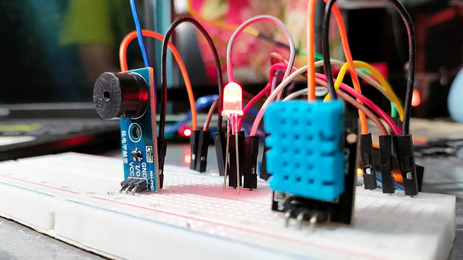
In this era of smart technology, building your own customized alarm system can be both fun and practical. In this article, we will guide you through creating a simple yet effective temperature-based alarm system using readily available components like the DHT11 sensor, a blinking LED, and an MH-FMD piezo buzzer module. This system will trigger an alert when the temperature surpasses a defined threshold, in this case, 35 degrees Celsius.
Components Required:
- DHT11 Temperature and Humidity Sensor (click here to learn more about this sensor)
- Arduino Uno (or any compatible microcontroller)
- Jumper wires
- 220-ohm resistor
- LED (any color)
- MH-FMD Piezo Buzzer Module (you may use an ordinary piezo buzzer) (click here to know more about this module)
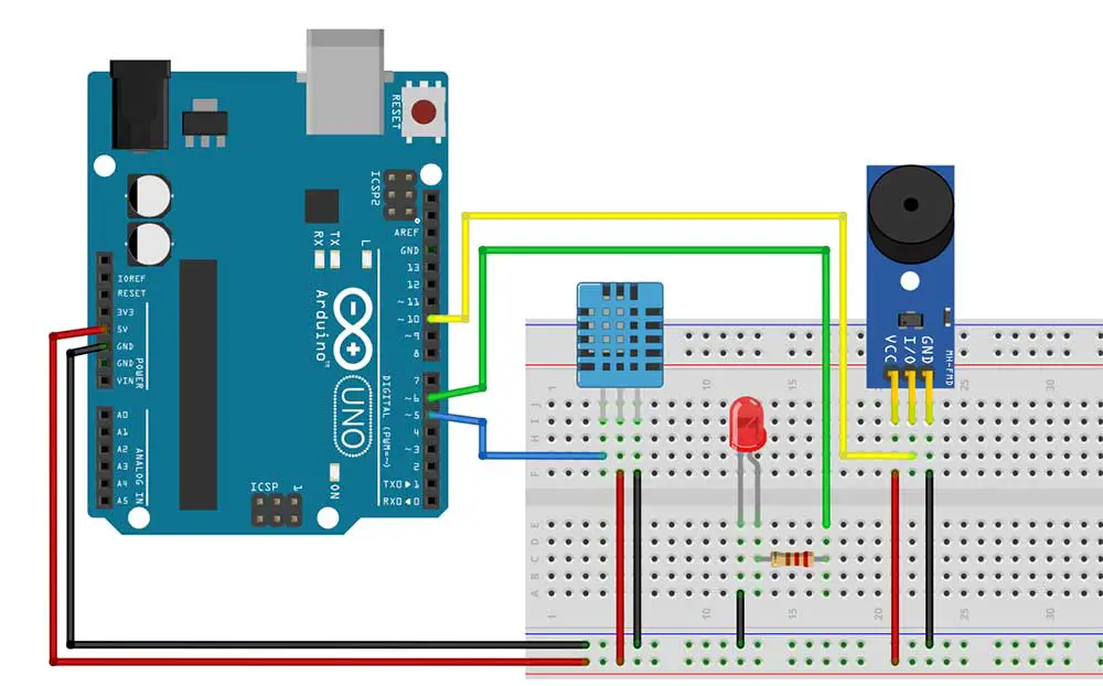
Setting Up the Circuit
Connect the DHT11 sensor to the Arduino:
- VCC pin of the DHT11 to 5V pin of the Arduino.
- Data/Signal pin of the DHT11 to digital pin 5 of the Arduino.
- GND pin of the DHT11 to GND pin of the Arduino.
Connect the LED:
- Anode (long leg) of the LED to digital pin 6 of the Arduino through a 220-ohm resistor.
- Cathode (short leg) of the LED to GND pin of the Arduino.
Connect the MH-FMD Piezo Buzzer Module:
- Connect the VCC pin to 5V pin of the Arduino.
- Connect the GND pin of the Piezo Buzzer Module to GND pin of the Arduino.
- Connect the I/O pin to pin 10 of the Arduino.
Here is the complete breadboard circuit:
Coding the Alarm System
We'll use the Arduino IDE to write the code for our alarm system. Make sure you have the necessary libraries installed for the DHT11 sensor.
#include <dht.h>
dht DHT11;

#define DHT11_PIN 5     // Digital pin connected to the DHT sensor

int ledPin = 6;
int buzzerPin = 10;
float tempThreshold = 35.0;

void setup() {
  pinMode(ledPin, OUTPUT);
  pinMode(buzzerPin, OUTPUT);
  Serial.begin(9600);
}

void loop() {

  float chk = DHT11.read11(DHT11_PIN);
  Serial.print("Temperature = ");
  Serial.println(DHT11.temperature);
  if (DHT11.temperature >= tempThreshold) {
    digitalWrite(ledPin, HIGH);
    tone(buzzerPin, 1000); // Turn on the buzzer
    delay(1000);           // Wait for 1 second
    digitalWrite(ledPin, LOW);
    noTone(buzzerPin);     // Turn off the buzzer
  }
  delay(2000);  //wait for 2 seconds to take the next reading
}
Explanation of the Code
- We define the pins for the DHT11 sensor, LED, and buzzer.
- In the setup() function, we set the LED and buzzer pins as output pins and initialize the DHT sensor.
- In the loop() function, we continuously read the temperature from the DHT sensor.
- If the temperature exceeds the defined threshold (tempThreshold), the LED will blink once and the buzzer will produce a sound for one second.
Let's break down the code step by step:
#include <dht.h>
This line includes the necessary library for the DHT11 sensor. Libraries provide pre-written code that simplifies programming by providing functions and definitions specific to certain hardware components. This library provides functions to interface with the DHT series of sensors, including the DHT11. Get the download and installation instructions for the DHT library here.
dht DHT11;
Here, we declare an object named DHT11 of type dht. This object will be used to interact with the DHT11 sensor.
#define DHT11_PIN 5 // Digital pin connected to the DHT sensor
This line defines a constant DHT11_PIN with the value 5, representing the digital pin to which the DHT sensor is connected.
int ledPin = 3;
int buzzerPin = 4;
These lines declare variables ledPin and buzzerPin to store the digital pins connected to the LED and buzzer, respectively.
float tempThreshold = 35.0;
This line declares a variable tempThreshold and initializes it to 40.0 degrees Celsius. This variable represents the temperature threshold beyond which the alarm will be triggered.
void setup() {
  pinMode(ledPin, OUTPUT);
  pinMode(buzzerPin, OUTPUT);
  Serial.begin(9600);
}
The setup() function:
- Sets the
ledPinandbuzzerPinas output pins usingpinMode(). This step configures these pins to send signals to control external devices (LED and buzzer). - Initializes the serial communication at a baud rate of 9600 bits per second using
Serial.begin(). This enables communication between the Arduino board and the computer via the USB cable. This allows us to print debugging information to the Serial Monitor in the Arduino IDE.
In the loop() function:
float chk = DHT11.read11(DHT11_PIN);
This line reads the temperature from the DHT11 sensor connected to pin 5 (DHT11_PIN). The temperature value is stored in the variable chk.
Serial.print("Temperature = ");
Serial.println(DHT11.temperature);
These lines print the temperature reading to the Serial Monitor for debugging purposes. You can open the Serial Monitor by going to Tools->Serial Monitor.
if (DHT11.temperature >= tempThreshold) {
Checks if the temperature read by the sensor (DHT11.temperature) is greater than or equal to the predefined threshold (tempThreshold).
    digitalWrite(ledPin, HIGH);
    tone(buzzerPin, 1000); // Turn on the buzzer
    delay(1000);           // Wait for 1 second
    digitalWrite(ledPin, LOW);
    noTone(buzzerPin);     // Turn off the buzzer
If the temperature exceeds the threshold:
- The LED pin (
ledPin) is set to HIGH to turn on the LED. - The
tone()function generates a 1000 Hz tone on thebuzzerPin, activating the buzzer. - The program pauses for 1 second using
delay(1000). - The LED pin is set to LOW to turn off the LED.
- The
noTone()function turns off the buzzer.
Troubleshooting Tips
Here are some troubleshooting tips if the Arduino project doesn't work as expected:
Check Connections:
- Ensure all connections between the Arduino board and components (DHT11 sensor, LED, buzzer) are correct and secure. A loose connection can prevent proper functionality.
Verify Power Supply:
- Confirm that the Arduino board is receiving power either from a USB connection or an external power source. Check if the LEDs on the board are illuminated, indicating power supply.
Test Individual Components:
- DHT11 Sensor: Verify that the sensor is functional by testing it separately with example code provided by the library. Ensure it's connected to the correct pin (pin 5 in this case).
- LED and Buzzer: Test the LED and buzzer independently by connecting them to power and ground pins to ensure they light up and emit sound, respectively.
Library and Code Issues:
- Ensure the DHT library is installed correctly in the Arduino IDE. Double-check the library name and version compatibility.
- Verify that the code is correctly written and uploaded to the Arduino board without any syntax errors.
- Check for any conflicts between pin assignments in the code and actual hardware connections.
Calibration and Thresholds:
- Adjust the temperature threshold (tempThreshold) in the code to a higher or lower value to test if the alarm triggers correctly.
- Check the temperature readings from the DHT11 sensor using serial monitoring to ensure they match the actual ambient temperature.
Debugging with Serial Monitor:
- Use the Arduino Serial Monitor to print debug messages or sensor readings to troubleshoot issues.
- Ensure that the sensor is providing accurate temperature readings and that the program logic is functioning as expected.
Inspect Hardware:
- Check for any physical damage or defects in the components, such as broken wires, damaged pins, or faulty connections.
- Ensure that the components are compatible with the Arduino board (e.g., voltage levels, current requirements).
Try Alternative Pins:
- If one digital pin doesn't work, try using a different pin on the Arduino board for connecting the sensor, LED, or buzzer.
Reset Arduino Board:
- Occasionally, resetting the Arduino board by power cycling it or pressing the reset button can resolve unexpected behavior.
Conclusion
By implementing this Arduino-based temperature monitoring and alert system, you can effectively safeguard your home against temperature-related risks and ensure a comfortable living environment for you and your family, even when you're not physically present.
With just a few components and a little programming, you've created a temperature-based alarm system using the DHT11 sensor, LED, and buzzer module. This simple yet effective system can be further customized and expanded to suit various applications, from monitoring room temperature to safeguarding sensitive equipment against overheating. Experiment with different thresholds and additional features to enhance its functionality. Happy tinkering!


