Can You Count People in a Room with a PIR Sensor, LCD, Buzzer, and Arduino?
If you're looking for an effective way to count the number of people entering and exiting a room, this guide will show you how to use a Passive Infrared (PIR) sensor, an LCD, a buzzer, and an Arduino to achieve this. This project is ideal for smart home systems, office management, or security applications, providing real-time monitoring and auditory alerts.
Counting the number of people in a room can be essential for managing room capacity, ensuring security, or monitoring foot traffic. By integrating a PIR sensor with an LCD and a buzzer using an Arduino, you can create a system that not only detects motion but also displays the count on an LCD and sounds an alert when someone enters or exits the room. This practical application is beneficial in various settings, such as offices, retail stores, and homes.
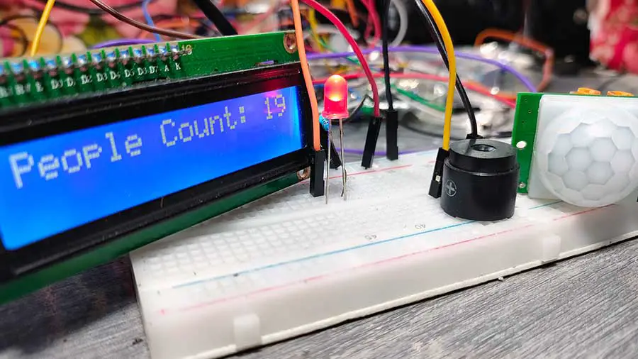
Here's a demo of my output:
Components Required
To build this project, you will need the following components:
- Arduino Uno or any compatible Arduino board
- PIR sensor
- 16x2 I2C LCD
- Piezo buzzer
- Breadboard
- Jumper wires
- LED (optional, for visual cue)
- 220-ohm resistor (optional, used with LED)
Setting Up the Hardware
First, let's connect the components according to the circuit below:
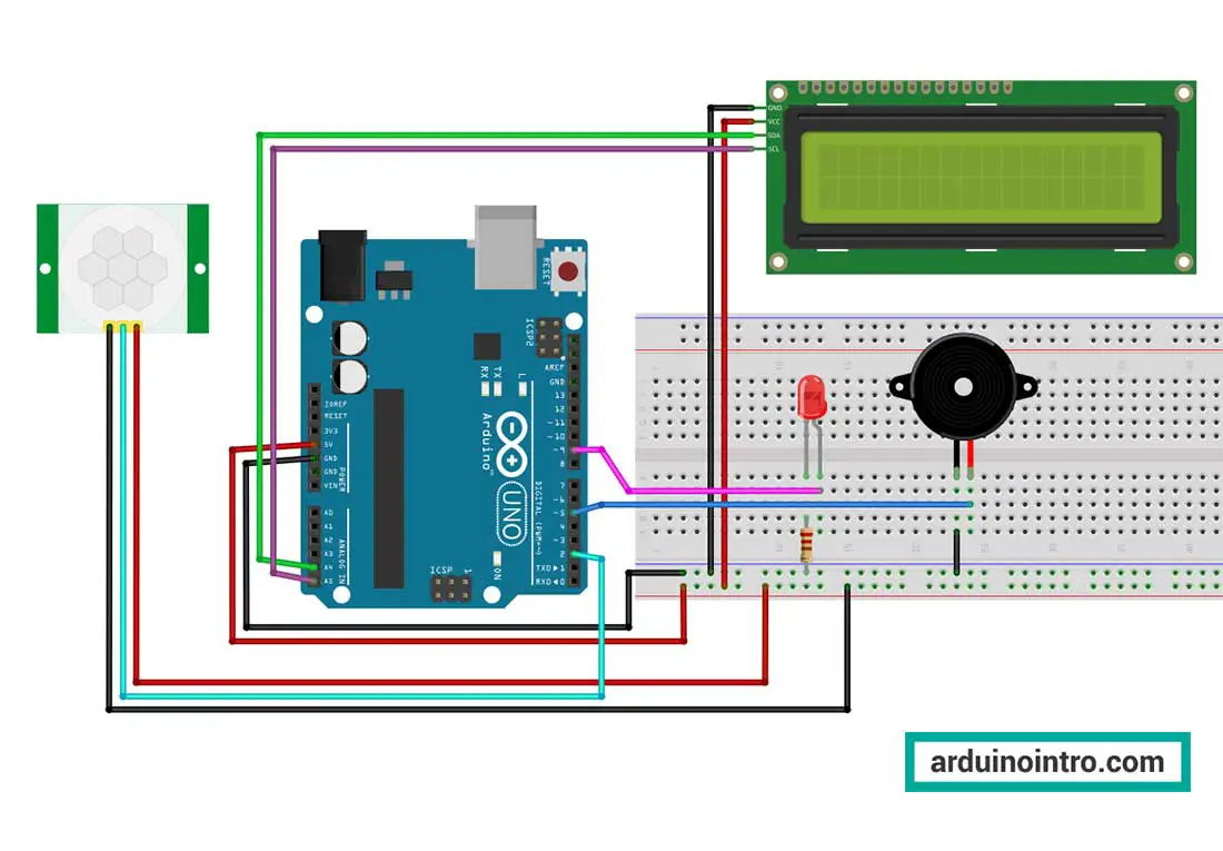
PIR Sensor Connections:
-
- VCC to Arduino 5V
- GND to Arduino GND
- OUT to Arduino digital pin 2
Read more about the PIR sensor used in this project: Exploring Home Automation: Integrating Passive Infrared Sensors with Arduino
I2C LCD Connections:
-
- GND to Arduino GND
- VCC to Arduino 5V
- SDA to A4
- SCL to A5
Read more about the I2C LCD used in this project: Displaying Characters Using the I2C Liquid Crystal Display (LCD)
Piezo Buzzer Connections:
-
- Positive lead to Arduino digital pin 5
- Negative lead to Arduino GND
Read more about the piezo buzzer used in this project: Exploring Piezo Buzzer Integration with Arduino: A Comprehensive Guide
Arduino Code
Here is the Arduino code to integrate the PIR sensor, LCD, and piezo buzzer:
#include <Wire.h>
#include <LiquidCrystal_I2C.h>

LiquidCrystal_I2C lcd(0x27, 2, 1, 0, 4, 5, 6, 7, 3, POSITIVE); //lcd is a user-defined name

int pirPin = 2; // PIR sensor input pin
int buzzerPin = 5; // Buzzer output pin
int ledPin = 9; // LED output pin

int pirState = LOW; // Initial state of PIR sensor
int peopleCount = 0; // Initial people count

void setup() {
  pinMode(pirPin, INPUT);
  pinMode(buzzerPin, OUTPUT);
  pinMode(ledPin, OUTPUT);

  lcd.begin(16, 2); // Set up the LCD's number of columns and rows
  lcd.print("People Counter");
  delay(2000);
  lcd.clear();
  lcd.print("Count: ");
  lcd.print(peopleCount);

}

void loop() {
  int motionDetected = digitalRead(pirPin);

  if (motionDetected == HIGH) {
    if (pirState == LOW) {
      peopleCount++;
      lcd.clear();
      lcd.print("People Count: ");
      lcd.print(peopleCount);
      digitalWrite(ledPin, HIGH);
      tone(buzzerPin, 1000); // Emit a sound
      delay(500); // Delay to allow for motion clearance
      noTone(buzzerPin);
      pirState = HIGH;
    }
  } else {
    if (pirState == HIGH) {
      pirState = LOW;
      digitalWrite(ledPin, LOW);
    }
  }

  delay(200); // Small delay to stabilize sensor readings
}
Code Explanation
Let's break down the code line-by-line:
#include <Wire.h>
#include <LiquidCrystal_I2C.h>
These lines include the necessary libraries for using I2C communication and the LiquidCrystal_I2C library, which enables communication with the LCD via I2C.
You may download the libraries here: Displaying Characters Using the I2C Liquid Crystal Display (LCD)
LiquidCrystal_I2C lcd(0x27, 2, 1, 0, 4, 5, 6, 7, 3, POSITIVE); //lcd is a user-defined name
This line initializes the LiquidCrystal_I2C object named 'lcd' with the address (0x27) of the LCD module, followed by the pins connected to the LCD (in the order: RS, EN, D4, D5, D6, D7, BL, BL_POL). 'POSITIVE' indicates that the LCD backlight polarity is positive.
int pirPin = 2; // PIR sensor input pin
int buzzerPin = 5; // Buzzer output pin
int ledPin = 9; // LED output pin
These lines declare integer variables to store the pin numbers for the PIR sensor, buzzer, and LED.
int pirState = LOW; // Initial state of PIR sensor
int peopleCount = 0; // Initial people count
These lines declare integer variables to track the state of the PIR sensor (initially LOW) and the count of people detected (initially 0).
void setup() {
  pinMode(pirPin, INPUT);
  pinMode(buzzerPin, OUTPUT);
  pinMode(ledPin, OUTPUT);

  lcd.begin(16, 2); // Set up the LCD's number of columns and rows
  lcd.print("People Counter");
  delay(2000);
  lcd.clear();
  lcd.print("People Count: ");
  lcd.print(peopleCount);
}
The 'setup()' function is executed once when the Arduino board is powered on or reset. Here's what each line does:
pinMode(pirPin, INPUT);andpinMode(buzzerPin, OUTPUT);: These lines set the pin modes for the PIR sensor and the buzzer.pinMode(ledPin, OUTPUT);: This line sets the pin modes for the LED.lcd.begin(16, 2);: This line initializes the LCD with 16 columns and 2 rows.lcd.print("People Counter");: This line prints "People Counter" on the LCD.delay(2000);: This line introduces a 2-second delay to allow time for the display to be read.lcd.clear();: This line clears all text printed to the LCD.lcd.print("People Count: ");: This line prints "People Count: " on the LCD.lcd.print(peopleCount);: This line prints the current value of 'peopleCount' on the LCD.
In short, the 'setup()' function initializes the pins for the PIR sensor, buzzer, and LED as INPUT or OUTPUT. It also initializes the LCD with 16 columns and 2 rows, prints "People Counter" on the LCD, waits for 2 seconds, clears the LCD, and prints "People Count: 0" to indicate the initial people count.
void loop() {
  int motionDetected = digitalRead(pirPin);

  if (motionDetected == HIGH) {
    if (pirState == LOW) {
      peopleCount++;
      lcd.clear();
      lcd.print("People Count: ");
      lcd.print(peopleCount);
      digitalWrite(ledPin, HIGH);
      tone(buzzerPin, 1000); // Emit a sound
      delay(500); // Delay to allow for motion clearance
      noTone(buzzerPin);
      pirState = HIGH;
    }
  } else {
    if (pirState == HIGH) {
      pirState = LOW;
      digitalWrite(ledPin, LOW);
    }
  }

  delay(200); // Small delay to stabilize sensor readings
}
The 'loop()' function continuously executes the code inside its curly braces. Here's a breakdown of each line:
int motionDetected = digitalRead(pirPin);: This line reads the digital input from the PIR sensor and stores it in the variable 'motionDetected'.
- The subsequent 'if' and 'else' statements check the value of 'motionDetected' to determine if motion is detected or not.
- If motion is detected (motionDetected == HIGH), the code inside the first 'if' block is executed:
if (pirState == LOW) {: This line checks if the PIR sensor state is LOW, indicating that no motion was previously detected.peopleCount++;: This line increments the 'peopleCount' variable to count the person who entered the room.lcd.clear();: This line clears the LCD.lcd.print("People Count: ");: This line prints "People Count: " on the LCD.lcd.print(peopleCount);: This line prints the updated value of 'peopleCount' on the LCD, indicating that a person entered the room and the current count of people.digitalWrite(ledPin, HIGH);: This line turns on the LED.tone(buzzerPin, 1000);: This line generates a tone on the buzzer with a frequency of 1000 Hz, indicating the detection of motion.delay(500);: This line introduces a 500-millisecond delay to allow time for motion clearance.noTone(buzzerPin);: This line stops the tone on the buzzer.pirState = HIGH;: This line updates the 'pirState' variable to HIGH, indicating that motion has been detected.
- If no motion is detected (motionDetected == LOW), the code inside the 'else' block is executed:
if (pirState == HIGH) {: This line checks if the PIR sensor state is HIGH, indicating that motion was previously detected.pirState = LOW;: This line updates the 'pirState' variable to LOW, indicating that no motion is currently detected.digitalWrite(ledPin, LOW);: This line turns off the LED.
Finally, there's a small delay at the end of the loop (delay(200);) to stabilize sensor readings before the next iteration.
To put it in simple terms:
The 'loop()' function continuously checks the state of the PIR sensor and performs the following actions:
- Reads the digital input from the PIR sensor.
- If motion is detected (motionDetected == HIGH) and the PIR state is LOW (indicating no previous motion):
- Increments the 'peopleCount' variable.
- Clears the LCD display, prints the updated people count, and turns on the LED.
- Emits a sound on the buzzer and introduces a 500 ms delay for motion clearance.
- Updates the 'pirState' variable to HIGH.
- If no motion is detected and the PIR state is HIGH:
- Updates the 'pirState' variable to LOW and turns off the LED.
Practical Application: Room Occupancy Monitoring System
This project can be effectively used to monitor room occupancy in various environments. For example, in an office setting, it helps manage meeting room availability by counting the number of people entering and exiting. In retail stores, it assists in understanding customer flow and optimizing staff allocation. Moreover, it can enhance security in restricted areas by alerting when unauthorized access occurs.
Conclusion
By following this guide, you have learned how to build a system using a PIR sensor, an LCD, and a piezo buzzer with an Arduino to count the number of people in a room. This project provides a practical solution for real-time monitoring and alerting, making it a valuable addition to smart home setups, offices, retail stores, and security systems. The skills and knowledge gained from this tutorial will empower you to create more advanced projects and explore further applications of PIR sensors and Arduino.
For more detailed projects and advanced tutorials, make sure to explore additional resources found on this site and continue experimenting with different sensors and components. Happy building!


I built this project as my first Arduino and trying to learn the programming. My counter resets at 100, how would I increase that value to 1000?
Hi Todd,
This could just be a problem of running out of columns to print on. That's why it seems the number resets at 100. Instead of writing this:
lcd.print("People Count: ");
write this, instead:
lcd.print("Count: ");
By reducing the number of characters, we increase the space available to print the counter.
Hope this helps.