Made by Maritess Marmito.
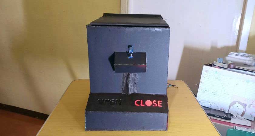
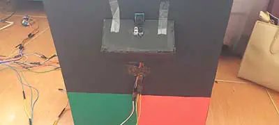
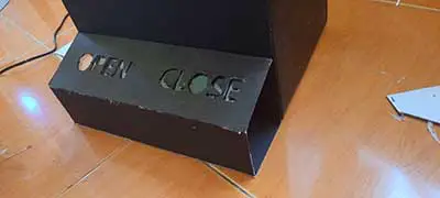
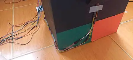
For this quarter my Exit Product is a DIY Smart Trash Bin. This is a robot designed for service and maintenance. In this project, I used only one sensor, which was an infrared sensor. This sensor is placed directly in front of the trash bin. When you place your hands, feet, or any object in front of the trash bin, the sensor detects it and emits a sound from the piezo buzzer, which is also located in front of the trash bin, near the infrared sensor, at the same time the trash bin lid opens and the four green LEDs at the bottom will light up. Furthermore, if the infrared sensor detects no object, the piezo buzzer will not make a sound and the other four red LEDs will light up. There are 8 LEDs in total because I labeled two words at the front bottom of the trash bin ('open' and 'close') and there are 4 green LEDs for the word 'open' and 4 red LEDs for the word 'close'.
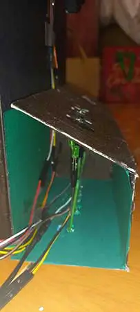
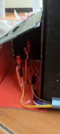
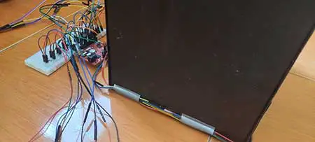
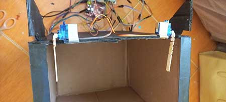
Additionally, for the connections. The sensor and buzzer are concealed by an illustration board with a shape that serves as its container, and for its connection, I made sure that its container has a hole in the bottom for the wires to pass through. Then there's another illustration board with a shape that serves as the enclosure for the LEDs. Inside this, I let the sensor and buzzer wires pass through, as well as the LED wirings.
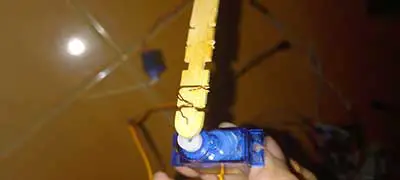
I also made a hole in the side of this enclosure so that the wires could pass through towards the Arduino board without destroying the beauty of the trash bin. Finally, the servo motors are located beneath the trash bin lid and are simply taped over with duct tape, while the wipers are tied with a popsicle stick and a small wire to make the wipers longer. Aside from that, all of the wires visible in the front and sides are covered with duct tape, and I simply place tissue paper on top of it so that I can paint the duct tape black because if I directly paint the duct tape, the paint will not stick and can be easily erased.
Materials needed
For the electronic connections:
- 8 LEDs
- Arduino Board
- USB interface
- Breadboard
- Jumper Wires
- Resistors
- Infrared sensor
- Piezo Buzzer
- Servo Motors
For the trash bin itself
- Illustration bored
- Used box
- Glue gun and Glue stick
- Popsicle sticks
- Glue
- Scissors and Cutter
- Paint and paint brush
- Small wire
- Colored papers
- Clear folder
- Duct tape
- Tissue
- Toothpick
STEP-BY-STEP PROCESS
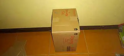
STEP 1
Gather all the materials.
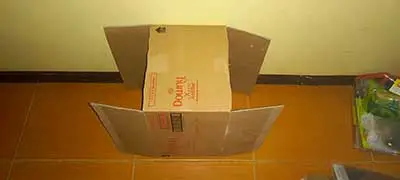
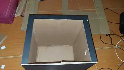
STEP 2
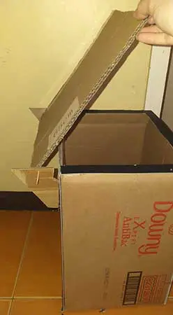
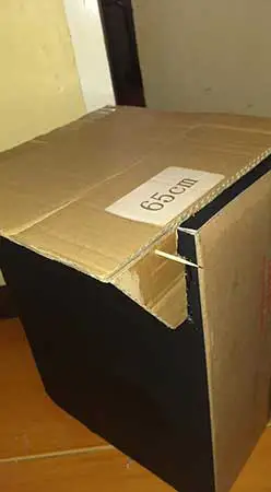
Cut the two small sides of the carton box as well as the top part, and glue the other two long sides together.
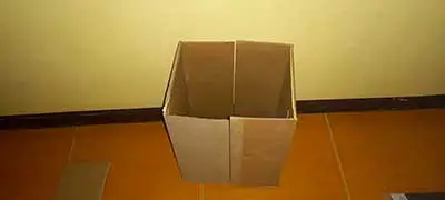
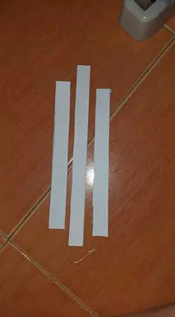
STEP 3
Cut three rectangular shapes and glue them together on all sides except the back part.
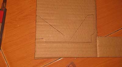
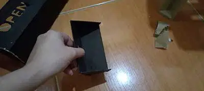
STEP 4
Cut two shapes like this and use a toothpick to make one hole in each.

STEP 5
Glue it to the back of the box, then take the lid off and insert the toothpick.
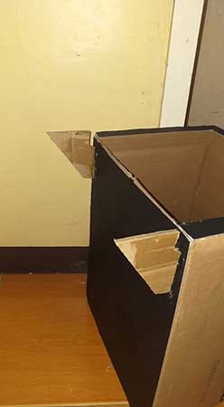
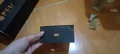
STEP 6
Cut out these shapes, cut a hole in the center for the Infrared sensor, and glue everything together.
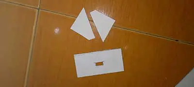
For reference (this is what it should look like)
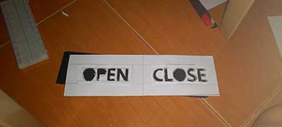
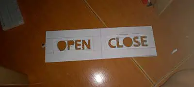
STEP 7
Make three rectangles out of the illustration board. Trace and cut out the words "open" and "close" in one of those rectangular shapes.
STEP 8
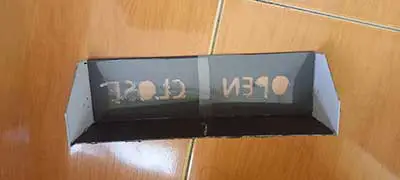
Glue the three rectangular shapes together and stick the clear folder beneath on rectangular shape with the cut-out words.
STEP 9
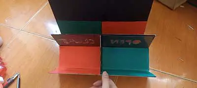
Insert a green piece of paper for the word "open" and a red piece of paper for the word "close" inside.

STEP 10
Cut out four popsicle sticks and glue them inside of the base, then tape the LEDs to each popsicle stick.
STEP 11
Cut this shape for the sides of the base, and make sure to cut a small rectangular shape for the wires to pass through.
STEP 12
In this cut-out illustration board, insert and tape the infrared sensor and buzzer.

Tape all of the wires together to keep them in place.
STEP 13
Insert this cut-out illustration with the LEDs and the words "open" and "close" and tape all of the LED wires together to keep them in place.

STEP 14
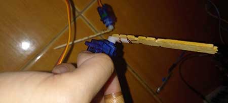
Tie the wipers together with a popsicle stick and a small wire to make them longer.
STEP 15
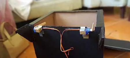
Under the trash bin lid, tape the servo motors to each side.
For the Arduino Circuit
STEP 1
I encoded the code. In this case, I used eight LEDs in total, but there is only one pin for two LEDs, so my code only shows four LEDs.
  #include <Servo.h>
  Servo s1;
  Servo s2;

  int ir =5; //IR sensor digital pin
  int pinServo1=9; //servo motor pin
  int pinServo2=6;
  int led1=1,led2=2,led3=10,led4=11;
  int val=0;
  int buzzer=7;


  void setup(){
    s1.attach(pinServo1);
    s2.attach(pinServo2);
    pinMode(led1,OUTPUT);
    pinMode(led2,OUTPUT);
    pinMode(led3,OUTPUT);
    pinMode(led4,OUTPUT);
    pinMode(ir, INPUT);
    pinMode(buzzer,OUTPUT);
  }

  void loop(){
    val = digitalRead(ir);

    if (val ==0) {
      s1.write(30);
      s2.write(140);
      digitalWrite(led3,HIGH);
      digitalWrite(led4,HIGH);
      digitalWrite(led1,LOW);
      digitalWrite(led2,LOW);

       tone(buzzer,500,500); //produce sound for 500 milliseconds
      //add a "quiet" time of 500 milliseconds
      delay(50);
        tone(buzzer,400,500); //produce sound for 500 milliseconds
      //add a "quiet" time of 500 milliseconds
       delay(50);
         tone(buzzer,300,500); //produce sound for 500 milliseconds
      //add a "quiet" time of 500 milliseconds
       delay(500);
    }
    else{
      s1.write(140);
      s2.write(30);
      digitalWrite(led3,LOW);
      digitalWrite(led4,LOW);
      digitalWrite(led1,HIGH);
      digitalWrite(led2,HIGH);

      delay(500);

    }
  }
STEP 2
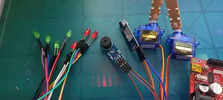
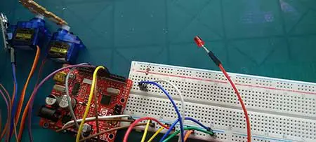
Gather the IR sensor, the Piezo Buzzer, and Servo Motors, then insert each of them with jumper wires.
STEP 3
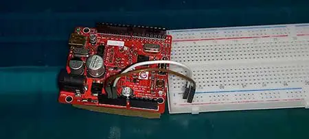
Connect GND and 5V to the breadboard.
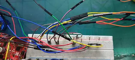
STEP 4
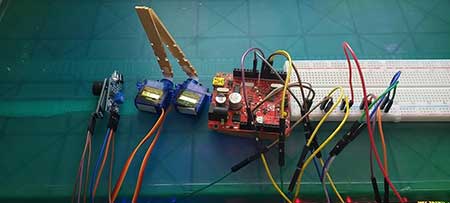
Connect all of the jumper wires from each sensor and the piezo buzzer to their respective Arduino and breadboard pins.
REMEMBER:
GND pin - GND pin of the Arduino board,
VCC - 5V pin,
D0 pin - any digital pin, except 0 and 1,
I/O – any digital pin (except 1 and 0),
OUT pin - any digital pin, except 0 and 1)
Servo Motor :
Brown wire goes to the GND Pin
Yellow wire goes to any digital pin
Red wire goes to the 5V pin
STEP 5
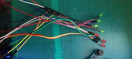
To make it longer, connect the LEDs to a jumper wire. Then repeat for all of the LEDs that will be used. This also applies to the piezo buzzer IR sensor and Servo Motors to make it longer.
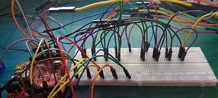
STEP 6
Connect the jumper wires of each LED to the breadboard, followed by the 2020k Ohm resistors on the LED's negative side. Then, for each led (anode of the LED), connect it to the digital pins of your Arduino board using jumper wires.
In my case, I was using the two sides of the breadboard and so I have to connect jumper wires with them to let the electricity pass through.
STEP 7
Upload the code to the Arduino board, and you'll have the go signal to play with it already.
Making my Arduino project for this quarter was not as simple as it appears. Initially, I planned to create an alcohol dispenser, but I assumed the servo motors have enough power to push the alcohol bottle. I want to make a lot more things besides trash cans because I think they're already common and basic, but I've opted to continue creating it. I then understand that it is alright for your project if it is already common as long as you gave it your all and it worked.
Considering that I am the type of student who will not settle for a basic project, I came up with the idea of using the LEDs in a creative way to add a little bit of uniqueness to my project and make the sensor, buzzer, and LEDs appealing while attempting to make cut out illustration boards that serve as sits enclosures.
After coming up with ideas, I attempted to write code for this project, and it took me a long time to do so, not because I was having difficulty, but because there was something wrong with my connections to the breadboard, which is why it wouldn't work, and all along trying to edit my code, I thought my code was the problem, but it wasn’t. I also struggled with making my trash can neat and hiding the wires because the wires are very distracting when they are not hidden.
Furthermore, despite the fact that I encountered a lot of difficulties while working on this project, I still had a lot of fun because I was motivated to finish it because I had imagined the outcome all along, and so working on it actually improved my mood because it is something that I enjoy doing, especially since I already have some basic knowledge about robotics.
Making these kinds of activities is what I prefer rather than doing essays or other written works.


