Made by Paolo Tuquib.
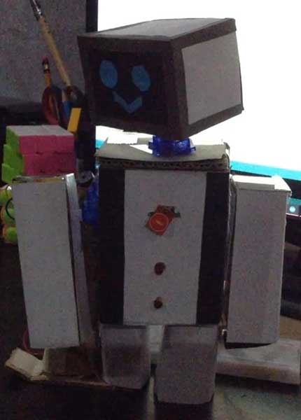
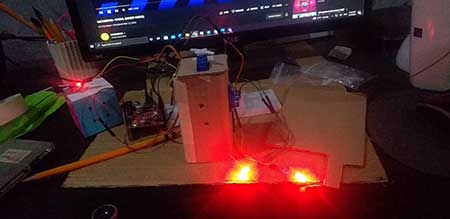
My exit product for this 3rd QTR. is a little entertainment robot named MERVO. This pandemic just seems to drag on and on, so a little bit of company would be helpful. Its movements simply comprise of moving its head left and right, and moving its left arm up and down, this is don’t through the servo motors. 2 red LEDs also light up on its torso. In order for MERVO to start moving, you must interact with the touch sensor found in its torso by touching it, and the animation will start to play. After it has finished, MERVO will play a short sound effect that indicates it is done.
The application of this robot is more on the Entertainment and Social Applications, as it provides company and something to toy with for a bit, especially in the coding part, amidst the pandemic, which is something that we all need when we are cooped up in our homes.
Materials
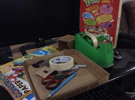
- Cardboard
- Colored construction paper
- Oslo Paper
- Scissors
- Masking Tape
- Adhesive Tape
- Glue
- Ruler
- pencil
- Cutter
- 2 Servo Motors
- 2 red LEDs
- 1 touch sensor
- 1 piezo buzzer
- Jumper wires
- gizDuino UNO-SE
- 220-ohm resistors
- Breadboard
Step-by-Step Process
Step 1. This code shows how MERVO is able to move through the servo motor coding, and how the other components work around it, such as the touch sensor initiating the entire animation, and the LEDs immediately lighting up in response. Lastly, how and when the piezo buzzer plays at the end of each.
#include <Servo.h>
Servo Serv1;
Servo Serv2;
int pinTS=8;
int pinServo1=5;
int pinServo2=6;
int pinLED1=2;
int pinLED2=3;
int buzzer=9;


void setup()
{
 Serv1.attach(pinServo1);
 Serv2.attach(pinServo2);
 pinMode(pinLED1, OUTPUT);
 pinMode(pinLED2, OUTPUT);
 pinMode(pinTS, INPUT);
 pinMode(buzzer,OUTPUT);
}


void loop() {
 if(digitalRead(pinTS) == HIGH)
 {

 digitalWrite(pinLED1, HIGH);
 digitalWrite(pinLED2, HIGH);
 Serv2.write(60);
 delay(2000);
 Serv1.write(60);
 delay(1000);
 Serv1.write(20);
 Serv2.write(140);
 delay(1000);
 Serv2.write(20);
 delay(500);
 Serv1.write(100);
 delay(2000);
 Serv2.write(60);
 delay(500);
 Serv1.write(90);
 delay(500);
 Serv1.write(40);
 delay(500);
 Serv1.write(90);
 delay(500);
 Serv1.write(40);
 delay(1000);
 Serv1.write(30);
 Serv2.write(30);
 delay(500);
 Serv1.write(60);
 Serv2.write(60);
 delay(500);
 Serv1.write(90);
 Serv2.write(90);

 delay(500);
 Serv1.write(110);
 Serv2.write(110);
 delay(500);
 Serv1.write(130);
 Serv2.write(130);
 delay(500);
 Serv2.write(60);
 delay(500);
 Serv1.write(20);
 delay(700);
 Serv1.write(50);
 delay(500);
 Serv1.write(120);
 delay(500);
 Serv1.write(50);
 delay(500);
 Serv1.write(120);
 delay(500);
 Serv1.write(50);
 delay(500);
 Serv1.write(120);
 delay(500);
 Serv1.write(50);
 delay(500);
 Serv1.write(120);
 delay(500);
 Serv1.write(50);
 tone(buzzer,1000,500);
 delay(500);
 tone(buzzer,1200,500);

 delay(500);
 tone(buzzer,1350,500);
 delay(500);
 tone(buzzer,1534,500);
 delay(500);
 delay(1500);


}

else
{
 Serv1.write(20);
 Serv2.write(20);
 digitalWrite(pinLED1, LOW);
 digitalWrite(pinLED2, LOW);
 delay(100);
}

}
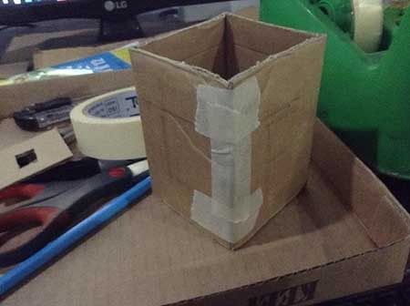
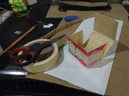
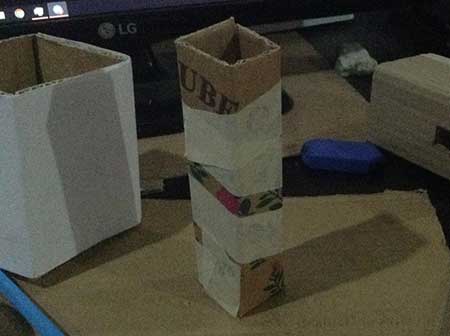
Step 2. Cut a piece of cardboard in order to create the torso, fold it together and tape to keep the form.
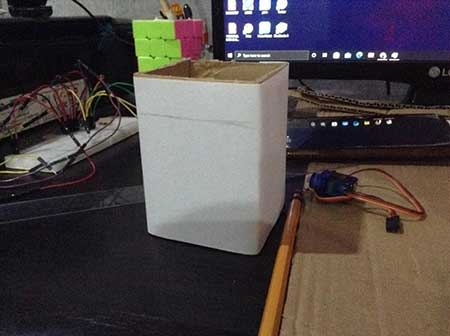
Step 3. Cover with Oslo paper as base.
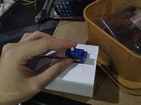
Step 4. Cut and punch appropriate-sized holes in the torso in order to fit the components later in the assembly, also a back hole for the passageway of the wires.
later:
Step 5. Cut a lightweight cereal box to allow for easier rotation of the servo motors on the head and the arms.
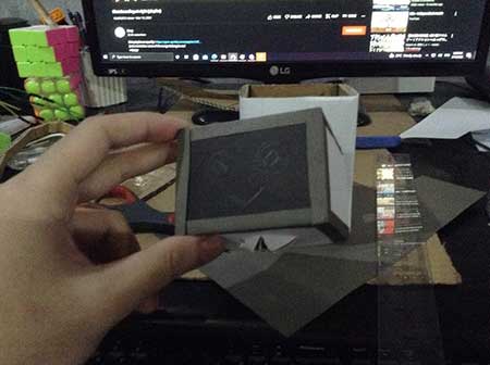
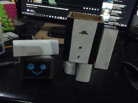
Step 6. Add a design to the head and the arms.
Step 7. Cut cardboard for the legs, fold, and tape to keep the form.
Step 8. Add finishing details to MERVO such as the back bars on the side of the torso, and a cheery smile.
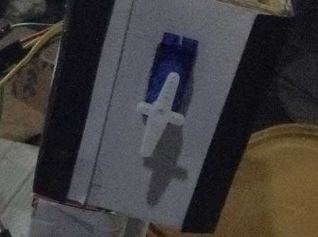
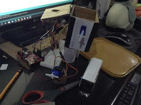
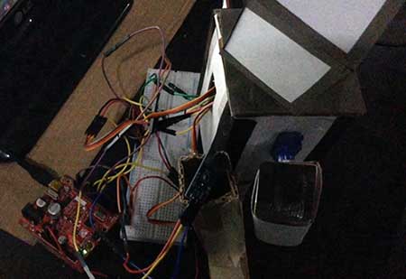
Step 9. With the hardware included, insert the wires through the back hole and into their respective places. The 2 circle holes for the LEDs, the 1 small slit hole for the touch sensor, and the holes located on the head and the arm for the servo motors. Then, assemble, tape, and secure the head and arm parts to the servo motors.
Throughout the process of making my exit product, I was focused and excited to see what the output would become, and how MERVO would look from what I had originally planned. Creating the frame of the robot took the longest part, but it was still fun to build the body of MERVO, and design it to look more appealing. But at the same time, I felt anxious because I could have messed up the process midway, and the servo motors would not be able to handle the weight of the parts.
That’s why I decided to use the cereal box as a lightweight material that can be rotated easier by the servo motor. Overall, the experience was very new to me, although I had already learned how to use most of the components thanks to past lessons. After finishing up another quarter of Robotics, I realized that I really like creating things, whether it would be through drawing, coding, or others.
With proper practice, posture, patience, focus, and time management, I would be able to enhance my skills for future projects.


