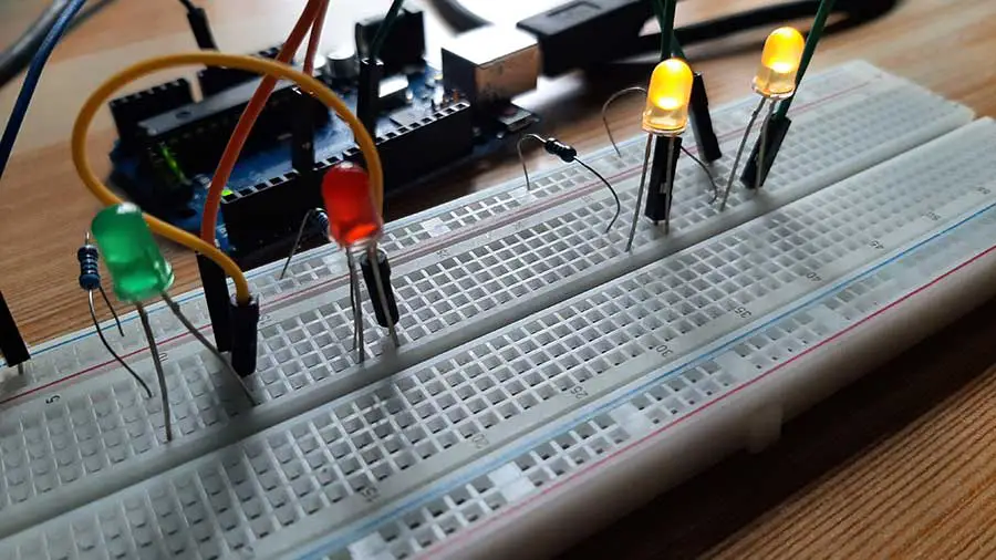
Compared with conventional light sources that first convert electrical energy into heat, and then into light, LEDs (Light Emitting Diodes) convert electrical energy directly into light, delivering efficient light generation with little-wasted electricity. When connected to an Arduino pin, it can brighten up a room. What happens when you put two LEDs in 1 pin? Well, you get two times the brightness.
Most common LEDs require a current rating of about 10 to 30 mA, with 12 to 20 mA being the most common range. The LED current must be less than the maximum permitted for your LED. For standard 5mm diameter LEDs the maximum current is usually 20mA, so 10mA or 15mA are suitable values for many circuits. Since an Arduino digital pin can supply around 40 milliamps of current, we can connect two LEDs in one pin. Three if you really want to stretch it out. Drawing a lot of milliamps in a single digital pin may damage the Arduino board or the electronic component attached to it.
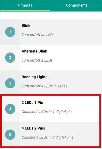
For this project, we’re using Project 4 and 5 of the Arduino Intro app. Let’s start with Project 4, connecting 2 LEDs in one digital pin. This project needs 2 LEDs and 2 220 ohm resistors.
You may also use 330-ohm resistors if you don’t have the 220. 330-ohm resistors have the colors orange-orange-brown. Anything higher than 330 is still ok, however, the brightness of the LED will be reduced.
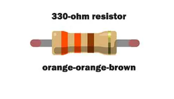
Don’t use resistors lower than 220 ohms, as it will let more current pass through the LED which is more than what it is rated for. Supplying too much current to the LED will damage it.
PROJECT: 2 LEDs, 1 Pin
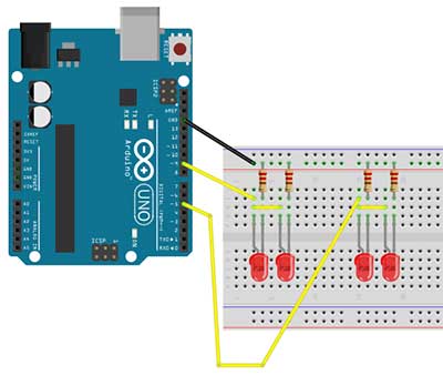
For the breadboard, the objective is to connect the positive sides of both the LEDs into just one digital pin. This will let us save some digital pins that can be used for other components. We will borrow a simple trick we learned from the running lights project to connect the positive sides. The trick is to connect a jumper wire from the positive side into one of the power rails.
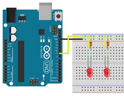
Although there are other ways to connect the 2 sides, this method will show us how the power rails on the edges of the breadboard are connected as compared to the terminal strips at the middle part. In this project, we will connect the positive sides to digital pin 9.
Again, the negative sides go through a resistor before it goes to the GND pin of the Arduino. This is similar to our running lights project.
Now, on to the code. If you look closely, this code is similar to our blinking light code, which is exactly what we want to happen.
	/*
	2 LEDs 1 pin
	(basically the same with blink sketch)
		1.	Turn on 2 LEDs for 1 second
		2.	Turn off 2 LEDs for 1 second
		3.	Repeat
	*/

	int pinled = 9;

	void setup() {
		// initialize the digital pin as an output.
		pinMode(pinled, OUTPUT);
	}

	// the loop routine runs over and over again forever:
	void loop() {
		digitalWrite(pinled, HIGH);   // turn the LED on
		delay(1000);               // wait for a second
		digitalWrite(pinled, LOW);    // turn the LED off
		delay(1000);               // wait for a second
	}
The difference here is that, instead of only 1 LED blinking, we now have 2 LEDs blinking at the same time. What we modified here is really on the hardware or electronic side of things. So basically, we declare a variable for digital pin 9. Set that pin as an output pin inside our setup function. And in the loop function, we just turn on pin 9 and after 1 second, we turn it off. We wait for another second before we turn it on again. And this goes on in a loop until there is no more power supplied to the Arduino board.
PROJECT: 4 LEDs, 2 Pins
Now let’s go to the next project, 4 LEDs in 2 Pins. By now, you should have an idea already of how to make the connections in the breadboard. This is another way to connect the positive sides of two LEDs. We just connect the two sides using a jumper wire and with another wire, connect them to digital pin 9. What we do next is just to replicate what we did with the previous pair of LEDs. Only here, the jumper wire is connected to pin 5. Perhaps, an important thing to remember here is that there should be a resistor connected to each LED.
The code is similar to the alternate blink project. Again we declare 2 variables on top, 1 for each pin. Variable pinLED1 for pin 9 and variable pinLED2 for pin 5.
	/*
	4 LEDs 2 Pins
		1.	Turn on the first pair of LEDs and turn off
			the other pair of LEDS at the same time,
			for 1 second.
		2.	Turn off the first pair of LEDs and turn on
			the other pair of LEDS at the same time,
			for 1 second.
		3.	Repeat
	*/

	int pinLED1=9,pinLED2=5;


	void setup() {
	// put your setup code here, to run once:
		pinMode(pinLED1,OUTPUT);
		pinMode(pinLED2,OUTPUT);
	}

	void loop() {
	// put your main code here, to run repeatedly:
		digitalWrite(pinLED1,LOW);
		digitalWrite(pinLED2,HIGH);
		delay(1000);
		digitalWrite(pinLED1,HIGH);
		digitalWrite(pinLED2,LOW);
		delay(1000);
	}
Then we set the 2 pins as OUTPUT pins inside the setup function. Inside the loop function, we first turned off pinLED1 by giving it a LOW value and we turned on pinLED2 by giving it a HIGH value. This state stays for 1 second as indicated by the delay function with 1000 milliseconds. After the delay, pinLED1 is then turned on while pinLED2 is turned off. A delay of 1 second is again written before it goes back at the top of the loop.
By connecting two or even three LEDs in one pin, we can increase the brightness of our LED lighting projects. However, I would strongly recommend using no more than three LEDs in one pin as it could cause erratic behavior on your project or it could potentially damage your Arduino board. Take note also to use connect 1 resistor for each LED you use.


I have a question. Can both leds run on a single resistor with less ohms? My reasoning being that since they run in parallel, the current is divided, so if there is a single resistor of, lets say 120ohm, would it be possible to use it instead of two 220ohm?
Or is it better to use 2x220ohm because if one led fails there is no excess current to the other led?
Im using a mega board for this exercise and space is very limited and I only have 1 gnd and 1 pin left and soldering 2 resistors would make it somewhat troublesome.
Thank you very much.
Hey Ralph,
Using a single resistor for multiple LEDs in parallel is generally not recommended. You are correct, if one LED fails, the current intended for both LEDs will pass through the remaining LED, potentially exceeding its current rating and causing it to fail as well.
Fantastic job, thank you once again.
You are welcome, good luck!
Yes, you can connect two LEDs in series with a 120Ω resistor, provided the total forward voltage is less than 5 volts. A typical forward voltage of a red LED is 2 volts. With two LEDs and using Ohm's Law, the current draw is 8.3mA, which is well within the recommended limit for an Arduino pin (20mA).