RGB LEDs are a great visual addition to your Arduino projects. Some of its applications include lighting systems that sync with music, changing mood lighting in rooms, and interface systems found in some robots. They can even be controlled using Bluetooth and a mobile app.
An RGB LED contains even tiny LEDs inside it with the colors red, green, and blue. The trick is just to control the brightness of each color so that the desired color will be achieved. For example, if the red and blue LEDs have maximum brightness and the green LED is turned off, then you will get a purple color.
An RGB LED normally has 4 pins or leads. The 3 leads are for the red, green, and blue light. If a stand-alone RGB LED is used, then a 220-ohm resistor is needed for each of these leads. The last lead is for the ground pin.
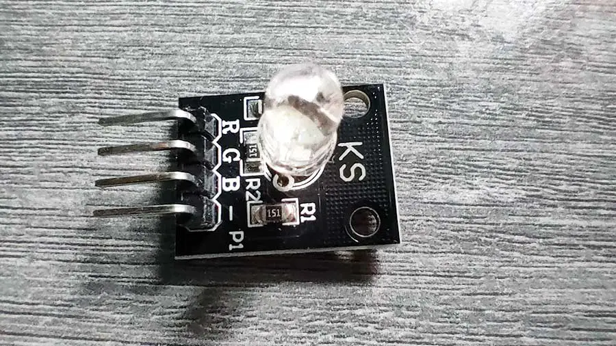
In this project, we will be using the KS RGB LED module. A module is better because the resistors are already built into the circuit. There is also another module called the KY-016 RGB module that works the same. The 2 RGB modules have a common cathode, meaning the R, G, and B LEDs all have a common ground.
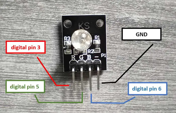
The KS RGB LED module also has 4 leads. The module I’m using has the following labels: R, G, B, -.
The R, G, and B, leads should go to PWM pins. In Arduino Uno, the PWM pins are digital pins 3,5,6,9,10, and 11. The – lead should go into the GND pin.
PROJECT 1: RGB LED Color Cycle
In this project, we will simply change the colors of the RGB LED every second, in this order:
|
COLOR |
RGB VALUE |
|
Red |
255, 0, 0 |
|
Green |
0, 255, 0 |
|
Blue |
0, 0, 255 |
|
Yellow |
255, 255, 0 |
|
Purple |
128, 0, 128 |
|
White |
255, 255, 255 |
|
Orange |
255, 165, 0 |
|
Cyan |
0, 255, 255 |
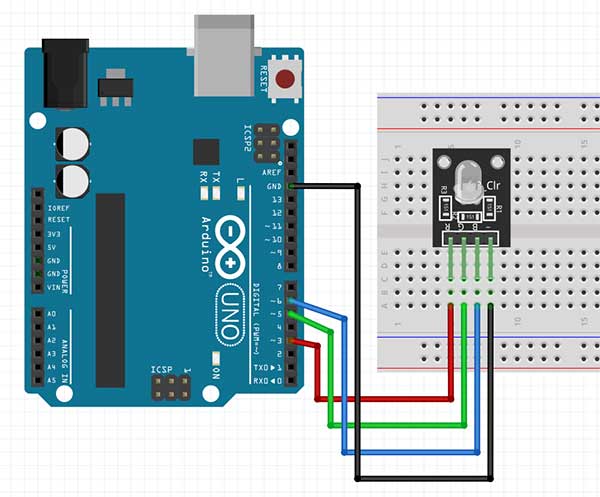
Here is the breadboard circuit:
Code:
  int r_led= 3;
  int g_led = 5;
  int b_led = 6;

  void setup() {
    pinMode(r_led, OUTPUT);
    pinMode(g_led, OUTPUT);
    pinMode(b_led, OUTPUT);
  }

  void loop() {
    ledColor(255, 0, 0); // red
    delay(1000);
    ledColor(0, 255, 0); // green
    delay(1000);
    ledColor(0, 0, 255); // blue
    delay(1000);
    ledColor(255, 255, 0); // yellow
    delay(1000);
    ledColor(128, 0, 128); // purple
    delay(1000);
    ledColor(255, 255, 255); // white
    delay(1000);
    ledColor(255, 165, 0); // orange
    delay(1000);
    ledColor(0, 255, 255); // cyan
    delay(1000);

  }

  void ledColor(int rValue, int gValue, int bValue) {
    analogWrite(r_led, rValue);
    analogWrite(g_led, gValue);
    analogWrite(b_led, bValue);
  }


Explanation:
  int r_led= 3;
  int g_led = 5;
  int b_led = 6;
We start by declaring the variables for the R, G, and B pins. Ensure you are using PWM pins because we will be writing analog values to these pins later.
  void setup() {
    pinMode(r_led, OUTPUT);
    pinMode(g_led, OUTPUT);
    pinMode(b_led, OUTPUT);
  }
For the setup() function, we simply need to declare all the pins as output pins.
The ledColor() Custom Function
ledColor(255, 0, 0); // red
Okay, the ledColor() function is not really a built-in function in Arduino (like setup(), delay(), etc.). It is what we call a custom function which is supposed to be written by the programmer. Functions help the programmer in making the code more organized and efficient.
According to Arduino, you may create your own function if you need to perform the same action multiple times in a program. When the need arises to perform the same action, you simply have to “call” the function and that function will promptly run whatever code is written inside it. Once the code is finished, it will go back to the main function that “called” it.
  void ledColor(int rValue, int gValue, int bValue) {
    analogWrite(r_led, rValue);
    analogWrite(g_led, gValue);
    analogWrite(b_led, bValue);
  }
In this project, notice that we created a function named ledColor() in the last 5 lines of our code. When writing your custom function, make sure that it is outside the setup() and loop() functions. Also, make sure that the name of your function is unique and does not already exist in Arduino. There are rules in naming a function, but for now, just make sure that the name is composed of small or capital letters, and that there are no spaces between the characters.
There's also a detailed explanation of RGB LED codes and Custom Functions in this article.
Function parameters
void ledColor(int rValue, int gValue, int bValue) {
When we wrote the ledColor() function, noticed that there were variables being declared inside the parentheses. These are called parameters. You can think of parameters as placeholders for values that you will be “passing” later on when you call this function. These parameters will then be used by the code found inside this function.
For example, in the line ledColor(255, 0, 0), the 255 is passed to the rValue parameter. rValue then becomes 255, which was used in the line analogWrite(r_led, rValue) found inside the ledColor() function. Pretty neat, isn’t it?
By writing it this way (using custom functions), you will avoid writing analogWrite() so many times. You will write the code sequence only once and then simply call the function to run it. In this project, we simply write the ledColor() function, along with its parameters for every second, instead of writing the 3 lines of analogWrite() functions.
PROJECT 2: Fading RGB LED Effect: Smooth Color Transition
For this project, we will slowly change or fade the color of our RGB LED module from red to green and vice-versa.
The breadboard circuit is the same as the previous project.
Arduino Sketch:
int r_led = 3; // select the pin for the red LED
int g_led = 5; // select the pin for the  blue LED
int b_led = 6; // select the pin for the green LED
int val;
void setup() {
  pinMode(r_led, OUTPUT);
  pinMode(g_led, OUTPUT);
  pinMode(b_led, OUTPUT);
}
void loop() {
  //fade from red to green
  //red is 255,0,0
  //green is 0,255,0
  for(val = 255; val > 0; val--)
  {
    analogWrite(r_led, val);
    analogWrite(g_led, 255 - val);
    analogWrite(b_led, 0);
    delay(10);
  }

  //fade from green to red
  for(val = 0; val < 255; val++)
  {
    analogWrite(r_led, val);
    analogWrite(g_led, 255 - val);
    analogWrite(b_led, 0);

    delay(10);
  }
}
Explanation
for(val = 255; val > 0; val--)
This line uses the for loop. The for loop has 3 parts, each separated by a semi-colon. The first part is the initialization of a variable that controls the loop. In this case, the variable val is initialized to 255. The second part contains the condition that controls when the loop runs or stops. In this case, the loop runs as long as the val variable is greater than 0. It stops when the val variable becomes 0 or less than 0. The last part should contain a code that changes the variable's value.
We could add something to the value of our variable or we could subtract. If the value does not change, then we could be stuck in an infinite loop. A thorough explanation of the for loop can be found in the Fade Effect article.
    analogWrite(r_led, val);
    analogWrite(g_led, 255 - val);
    analogWrite(b_led, 0);
    delay(10);
If we start the loop, the actual code that is run by Arduino will look like this
    analogWrite(r_led, 255);
    analogWrite(g_led, 0); //255-255
    analogWrite(b_led, 0);
    delay(10);
Notice that the val variable was changed to its actual value which is 255. Now the next time the loop will run, the val variable will become 254. This is because of this code: val--. This means that Arduino will subtract 1 from the current value of the val variable, hence, 254. The next time the loop runs, it will look like this:
    analogWrite(r_led, 254);
    analogWrite(g_led, 1); //255-254
    analogWrite(b_led, 0);
    delay(10);
This goes on and on until the val variable becomes less than 0. Take note that the next loop takes place after 10 milliseconds because of this code: delay(10). So we can already picture that the LED’s color changes slowly every 10 milliseconds.
//fade from green to red
  for(val = 0; val < 255; val++)
The next set of for loop uses the same principle as the previous set. Only this time the initial value of the val variable is 0, and it continues to run until the val variable becomes greater than 255.


