Step into the world of home automation with a simple yet fascinating project that involves controlling a 220-volt light bulb using an Arduino and a relay module. This project not only introduces you to the basics of Arduino programming but also demonstrates how to manage high-voltage devices with ease.
Imagine the convenience of turning a 220- to 250-volt light bulb on and off at the push of a button or even remotely via a smartphone. This guide will walk you through three engaging projects, perfect for beginners, and show you how to master the use of a relay module with your Arduino.
What is a Relay Module?
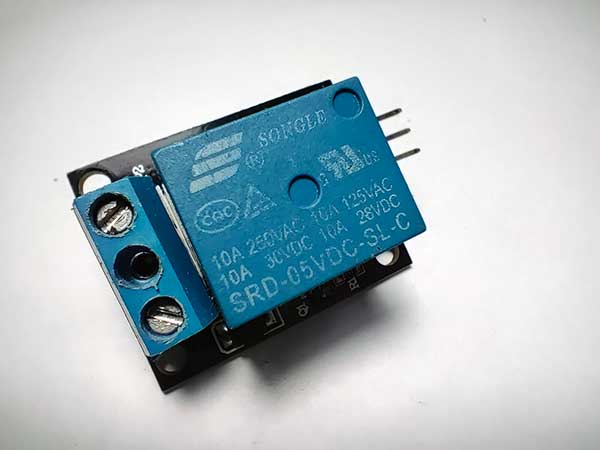
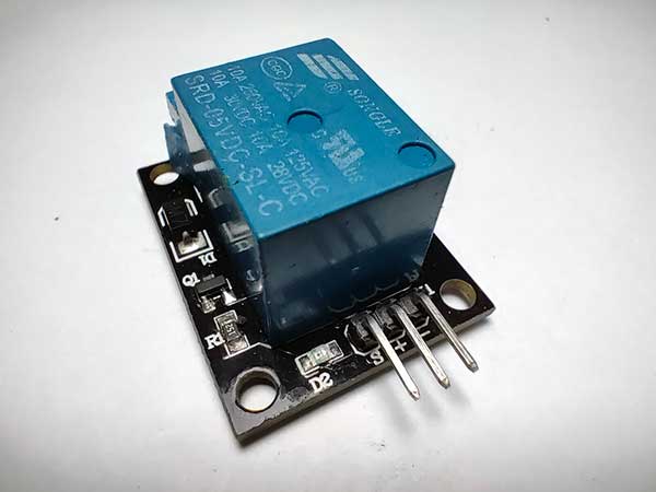
A relay module is an electrically operated switch that allows you to control a high-voltage circuit with a low-voltage signal from an Arduino. It's a crucial component for projects that involve controlling appliances or other high-power devices. The relay module can isolate the low-voltage side (Arduino) from the high-voltage side (light bulb), providing safety and flexibility in your projects.
Normally Open (NO) and Normally Closed (NC) Features
Relay modules typically have three main contacts:
- Common (COM): This is the common terminal.
- Normally Open (NO): When the relay is not energized, there is no connection between COM and NO. When the relay is energized, COM and NO are connected, allowing current to flow.
- Normally Closed (NC): When the relay is not energized, COM and NC are connected, allowing current to flow. When the relay is energized, the connection is broken.
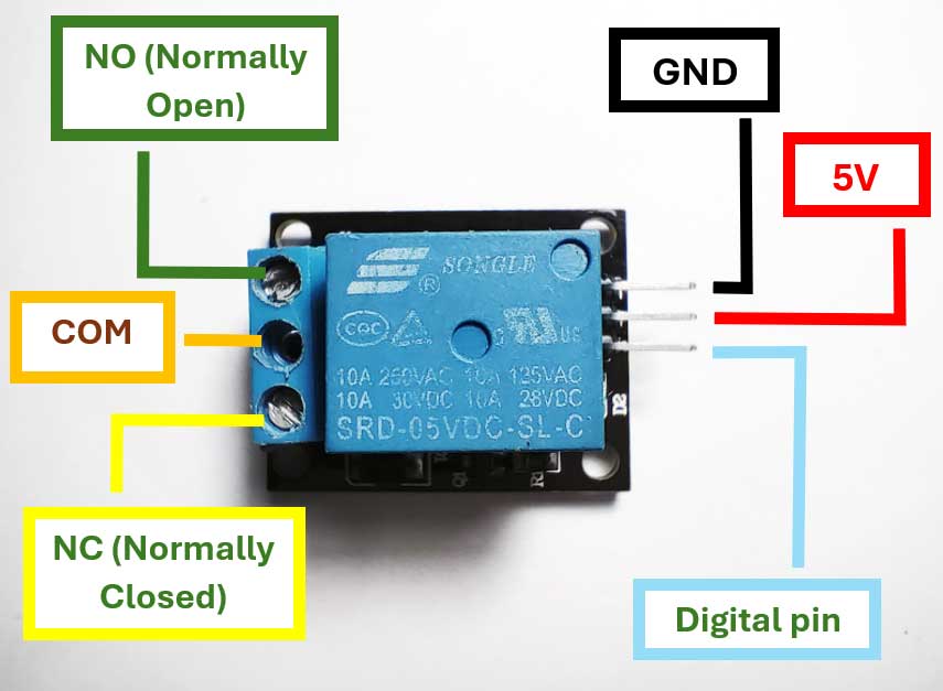
For most applications, including this one, the Normally Open (NO) configuration is used. This means the circuit is only completed (and the light bulb is turned on) when the relay is activated.
Safety Warning
Before proceeding with these projects, please be aware that you will be working with mains electricity (220-250 volts). It is crucial to follow safety precautions to prevent electrical shock or fire hazards. If you are not experienced with working on mains electricity, seek help from a professional or someone with experience.
Project Overview
Components Needed:
- Arduino Uno
- Relay Module (suitable for 220-250V operation)
- 220- to 250- Volt Light Bulb
- Breadboard
- Jumper Wires
- External Power Source (for Arduino)
- 220-ohm Resistor
- Push Button (optional for the second project)
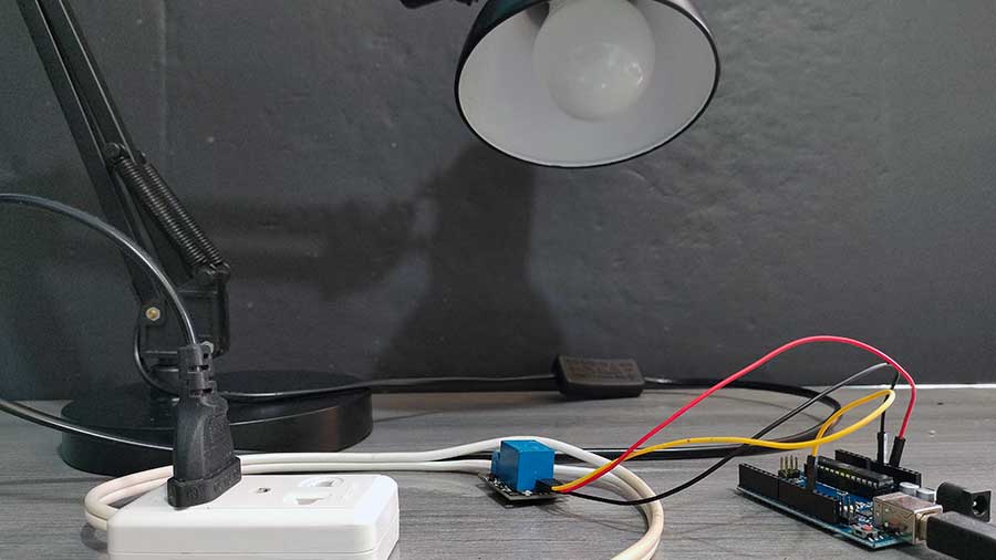
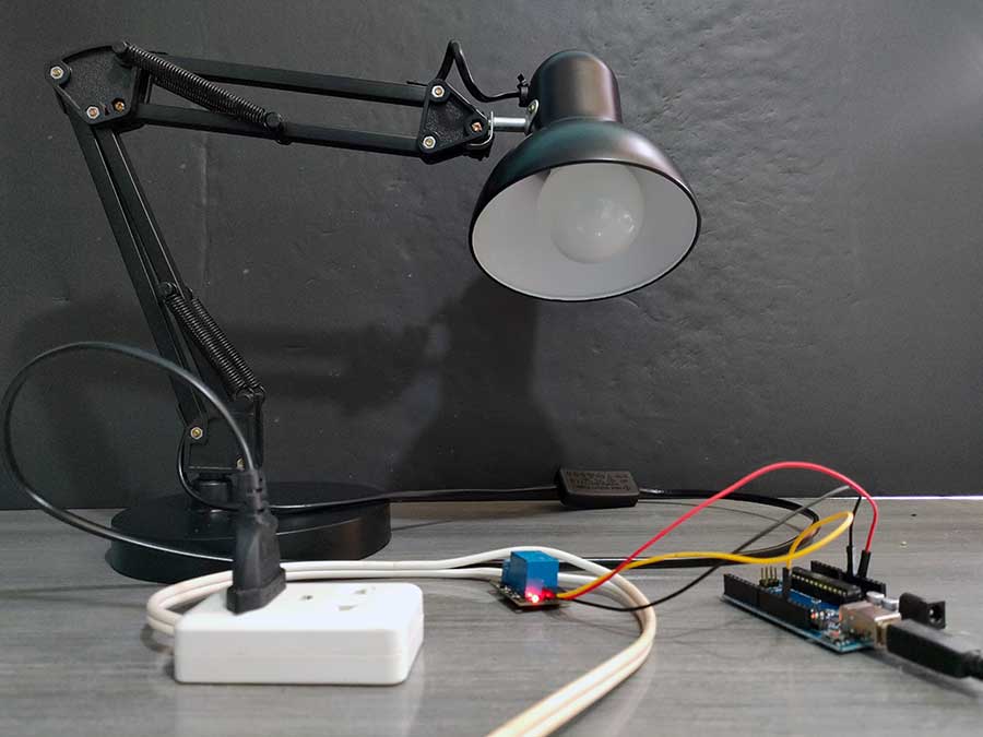
Project 1: Blinking Light Bulb
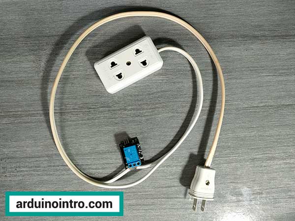
This is what it's going to look like:
Step 1: Setting Up the Hardware
-
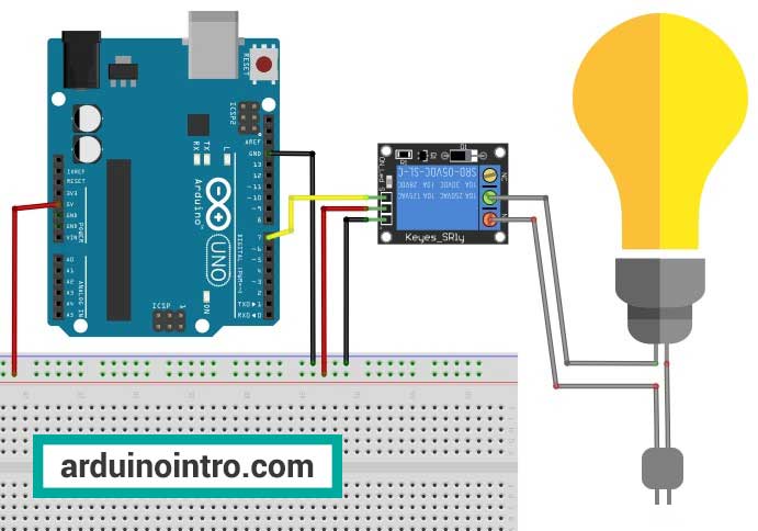
Connect the Relay Module to the Arduino:
- VCC of the relay module to 5V on the Arduino.
- GND of the relay module to GND on the Arduino.
- IN pin of the relay module to digital pin 7 on the Arduino.
-
Connect the Light Bulb to the Relay Module:
- One terminal of the light bulb to the normally open (NO) terminal of the relay.
- The other terminal of the light bulb to the common (COM) terminal of the relay.
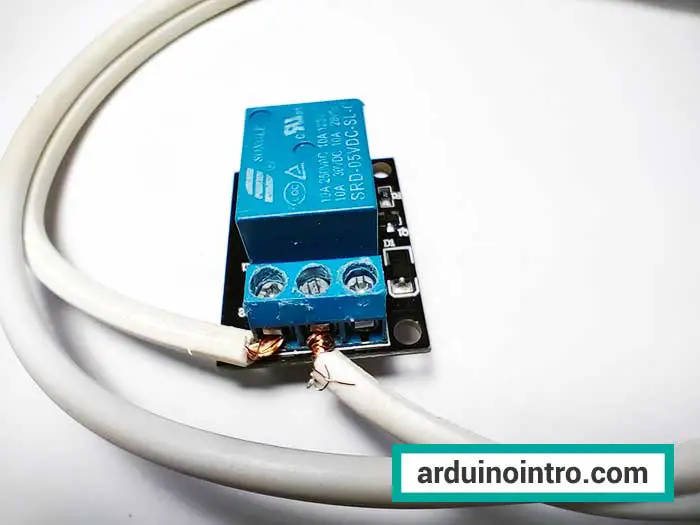
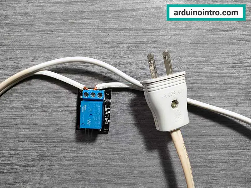
- Connect the mains power supply to the relay module:
- Live wire to the COM terminal of the relay.
- Neutral wire to one terminal of the light bulb.
- The other terminal of the light bulb to the NO terminal of the relay.
Step 2: Writing the Arduino Code
// Define pin number for the relay
int relayPin = 7;

void setup() {
  // Initialize the relay pin as an output:
  pinMode(relayPin, OUTPUT);
}

void loop() {
  // Turn relay on (light bulb on)
  digitalWrite(relayPin, HIGH);
  delay(1000); // Wait for a second

  // Turn relay off (light bulb off)
  digitalWrite(relayPin, LOW);
  delay(1000); // Wait for a second
}
Step-by-Step Explanation of the Code
-
Define Pin Number:
int relayPin = 7;- Assigns digital pin 7 to the relay.
-
Setup Function:
pinMode(relayPin, OUTPUT);- Sets the relay pin as an output.
-
Loop Function:
digitalWrite(relayPin, HIGH);- Turns the relay on, which lights up the bulb.delay(1000);- Waits for one second.digitalWrite(relayPin, LOW);- Turns the relay off, which turns off the bulb.delay(1000);- Waits for one second.
This simple code will make the light bulb blink on and off every second.
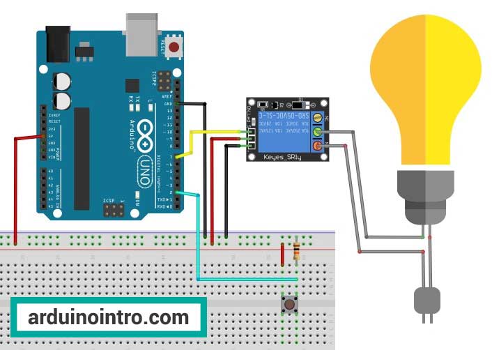
Project 2: Control Light Bulb with a Pushbutton
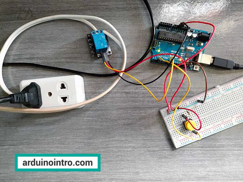
Here is a video of this project:
Step 1: Setting Up the Hardware
-
Connect the Relay Module to the Arduino:
- VCC of the relay module to 5V on the Arduino.
- GND of the relay module to GND on the Arduino.
- IN pin of the relay module to digital pin 7 on the Arduino.
-
Connect the Light Bulb to the Relay Module:
- One terminal of the light bulb to the normally open (NO) terminal of the relay.
- The other terminal of the light bulb to the common (COM) terminal of the relay.
- Connect the mains power supply to the relay module:
- Live wire to the COM terminal of the relay.
- Neutral wire to one terminal of the light bulb.
- The other terminal of the light bulb to the NO terminal of the relay.
-
Connect the Push Button to the Arduino:
- Connect one side of the push button to 5V on the Arduino.
- Connect the other side to digital pin 2 on the Arduino with a 220-ohm resistor.
- Connect the other side of the resistor to GND.
Step 2: Writing the Arduino Code
// Define pin numbers
int relayPin = 7;
int buttonPin = 2;

// Variables to hold button state
int buttonState = 0;

void setup() {
  // Initialize the relay pin as an output:
  pinMode(relayPin, OUTPUT);
  // Initialize the button pin as an input:
  pinMode(buttonPin, INPUT);
}

void loop() {
  // Read the state of the push button value:
  buttonState = digitalRead(buttonPin);

  // Check if the push button is pressed.
  // If it is, the buttonState is HIGH:
  if (buttonState == HIGH) {
    // Turn relay on
    digitalWrite(relayPin, HIGH);
  } else {
    // Turn relay off
    digitalWrite(relayPin, LOW);
  }
}
Step-by-Step Explanation of the Code
-
Define Pin Numbers:
int relayPin = 7;- Assigns digital pin 7 to the relay.int buttonPin = 2;- Assigns digital pin 2 to the push button.
-
Setup Function:
pinMode(relayPin, OUTPUT);- Sets the relay pin as an output.pinMode(buttonPin, INPUT);- Sets the button pin as an input.
-
Loop Function:
buttonState = digitalRead(buttonPin);- Reads the state of the button pin.- Checks if the button is pressed:
- If
buttonStateis HIGH, the relay is turned on (digitalWrite(relayPin, HIGH);). - If
buttonStateis LOW, the relay is turned off (digitalWrite(relayPin, LOW);).
- If
This code allows you to control the light bulb using a push button.
Project 3: Control Light Bulb with a Pushbutton Toggle Behavior
This is the final output:
Step 1: Setting Up the Hardware
Use the same hardware setup as Project 2.
Step 2: Writing the Arduino Code
This code is designed to control a relay, which in turn can control a high-voltage appliance (up to 250V) using a push button. The behavior is such that pressing and releasing the button once will turn the appliance on, and pressing it again will turn it off. This is often referred to as a "toggle" or "sticky" push button behavior.
 /*
  The "sticky" push button
  Light bulb turns on when pushbutton is pressed and released once.
  Light bulb off when pushbutton is pressed again.
  */

  // Define pin numbers
  int relayPin = 7;
  int buttonPin = 2;

  int val =0;
  int ledstate=LOW; //initial value

  void setup()
  {
    pinMode(buttonPin, INPUT);
    pinMode(relayPin, OUTPUT);
  }

  void loop()
  {
    val=digitalRead(buttonPin);

    if(val == HIGH) //button is pressed
    {
      //reverse the current state of the ledstate variable
      ledstate=!ledstate;
      digitalWrite(relayPin, ledstate);
      //wait 1 second before the next reading to ensure stability
      delay(1000);
    }

  }
Step-by-Step Explanation
Initializing Variables:
int val = 0;         // Variable to store the state of the button
int ledstate = LOW;  // Initial state of the relay (light bulb off)
val is used to store the state of the push button (HIGH or LOW). ledstate stores the state of the relay, starting with the light bulb off (LOW).
Main Loop Function:
void loop()
{
  val = digitalRead(buttonPin);  // Read the state of the push button
This line reads the current state of the push button and stores it in the val variable.
Checking Button State:
if (val == HIGH)  // If the button is pressed
{
  // Reverse the current state of the ledstate variable
  ledstate = !ledstate;  // Toggle the state (if LOW, set to HIGH; if HIGH, set to LOW)
  digitalWrite(relayPin, ledstate);  // Set the relay to the new state

  // Wait 1 second before the next reading to ensure stability and debounce the button
  delay(1000);
}
if (val == HIGH): This checks if the button is pressed.ledstate = !ledstate;: This toggles theledstatevariable. If it wasLOW(0), it becomesHIGH(1), and vice versa.digitalWrite(relayPin, ledstate);: This sets the relay pin to the new state ofledstate, effectively turning the relay (and thus the light bulb) on or off.delay(1000);: This introduces a 1-second delay to debounce the button, ensuring it doesn’t register multiple presses due to mechanical bouncing.
Summary of the Project
When you press and release the button:
- If the light bulb is off, it will turn on.
- If the light bulb is on, it will turn off.
The delay helps to avoid detecting the same button press multiple times due to mechanical noise. This code can be used to control any appliance up to 250 volts using a relay module and an Arduino, making it a great starting point for home automation project
Practical Application
These projects can be expanded to control other household appliances such as fans, lamps, or even your coffee maker. By integrating it with a wireless module like the ESP8266, you can create a remote control system for your devices, enhancing your home automation setup.
Common Questions
Q: Can I use a different light bulb or power source?
A: Yes, you can use different light bulbs and power sources as long as they match the specifications of your relay module and the external power source. Make sure to check the voltage and current ratings.
Q: Is it safe to use a relay module for home appliances?
A: Relays are designed for such purposes, but safety precautions should always be taken. Ensure your relay can handle the voltage and current of the appliance, and never work on live circuits.
Q: Can I automate these projects?
A: Absolutely! By incorporating sensors or wireless communication modules, you can automate and remotely control your light bulb. For example, using an ESP8266 module, you can control the light via a smartphone app.
Conclusion
Building projects to control a 220- to 250-volt light bulb with an Arduino and a relay module is an excellent way to learn about basic electronics and Arduino programming. These projects not only provide hands-on experience but also open up numerous possibilities for home automation and other practical applications. By following this guide, you will have functional setups that you can further expand and customize.
Remember to always prioritize safety when working with electrical components and enjoy your journey into the world of Arduino projects!


