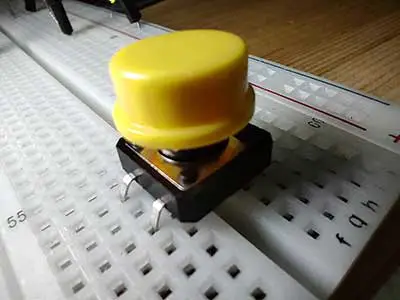
Tactile switches, sometimes called pushbutton switches are a type of switch that focuses on producing a tactile bump and a relatively quiet audible click when pressed. These small-sized switches are placed on PCBs and are used to close an electrical circuit when the button is pressed by a person. When the button is pressed, the switches turn ON and when the button is released, the switches turn OFF. The click response of the button lets the user feel the response of the operation from the switch.
From vending machines to measuring devices, tactile switches are ideal for enabling users to have the functions they need. Additional applications for tactile switches are control panels on printers and copiers, TV remote controls, and computer keyboards.
PROJECT 1: Push the Button
Pushbutton Switch as a Simple Sensor
Until now, we have only used the Arduino to control other things. It is time for us to start sensing the real world! After we do this, then our Arduino will be able to make decisions of what to do based on input from the outside world.
What’s missing to complete this picture is a sensor. In this case, we’re going to use the simplest form of sensor available: a pushbutton switch.
Pushing a button causes wires under the button to be connected, allowing current to flow (this is called the closed state) When the button isn’t pressed, no current can flow because the wires aren’t touching (this is called the open state).
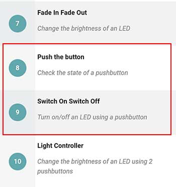
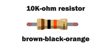
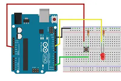
In this article, we’re going to make Projects 8 and 9 of the Arduino Intro app. We’ll just have to modify our breadboard diagram to add a 10K ohm resistor for the pushbutton to make it more stable. A 10,000-ohm or 10K-ohm resistor is colored brown-black-orange.
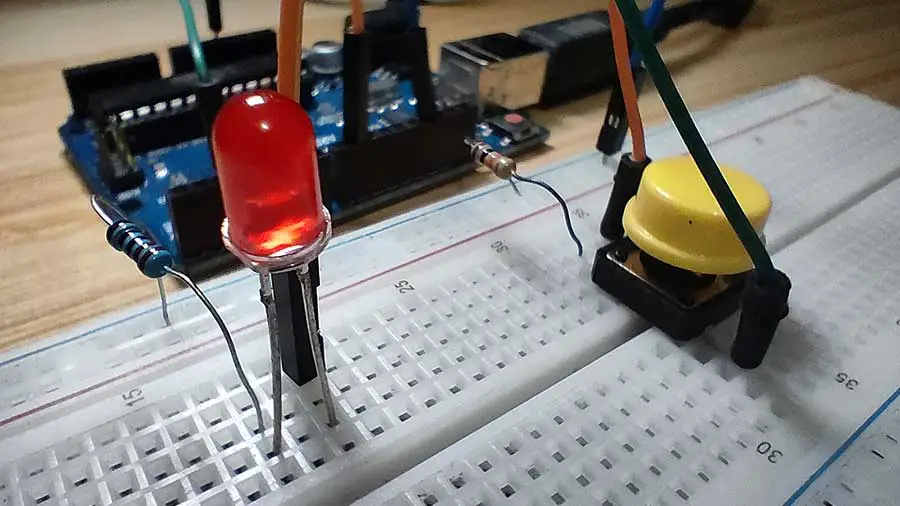
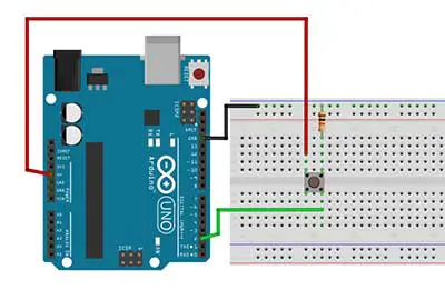
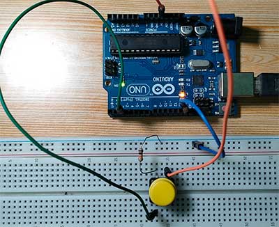
The Pushbutton Breadboard Circuit
We connect three wires to the board. The first two will be connected to the power rails on the side of the breadboard to provide access to the 5 volt supply and ground. The third wire goes from digital pin 2 to one leg of the pushbutton. That same leg of the button connects through a pull-down resistor (which is the 10K ohm resistor) to the ground. The other leg of the button connects to the 5 volt supply.
When the pushbutton is open (not pressed) there is no connection between the two legs of the pushbutton, so the pin is connected to the ground (through the pull-down resistor) and we read a LOW. When the button is closed (pressed), it makes a connection between its two legs, connecting the pin to 5 volts, so that we read a HIGH.
If you disconnect the digital I/O pin from everything, the LED may blink erratically. This is because the input is "floating" - that is, it will randomly return either HIGH or LOW. That's why you need a pull-up or pull-down resistor in the circuit.
Reading the Pushbutton’s Value
To monitor the state of a switch, there’s a new Arduino instruction that you’re going to learn: the digitalRead() function. digitalRead() checks to see whether there is any voltage applied to the pin that you specify between parentheses, and returns a value of HIGH or LOW, depending on its findings. The other instructions that you’ve used so far, such as the digitalWrite, haven’t returned any information—they just executed what we asked them to do. With digitalRead(), you can “ask a question” from the Arduino and receive an answer that can be stored in memory somewhere and used to make decisions immediately or later.
Let’s examine the code for Project 8. This project simply tells us the current state of the pushbutton, whether it’s pressed or not pressed.
// Read the value of a pushbutton

int PinButton1 = 2;
int val=0;


void setup() {

  pinMode(PinButton1, INPUT);

  // initialize serial communication at 9600 bits per second:
  Serial.begin(9600);
}

// the loop routine runs over and over again forever:
void loop() {

  val= digitalRead(PinButton1);
  // print the value on the serial monitor
  //Go to Tools->Serial Monitor to see the values
  Serial.println(val);
  delay(100);
}
We will also use the Serial monitor feature of the Arduino to display the current state of the pushbutton on the computer monitor.
The first part of the code is the declaration of variables. Digital pin 2 is assigned to the PinButton1 variable. We also declared another variable called val. This variable is where we will save the current state of the pushbutton which we will then display on the screen.
pinMode(PinButton1, INPUT);In the setup function, you’ll notice that we have set up digital pin 2 as an INPUT pin. This is because we are going to use the pushbutton which is attached to pin 2 as an input device. Since we already added a pullup resistor in our circuit there’s no need to enable the internal pull resistor of our Arduino board.
Serial.begin(9600);Lastly, if we want to display characters on the screen, then we will initialize the Serial function using the Serial.begin(9600) statement. 9600 is called the baud rate. The baud rate is the rate at which information is transferred in a communication channel. Baud rate is commonly used when discussing electronics that use serial communication. In the serial port context, "9600 baud" means that the serial port is capable of transferring a maximum of 9600 bits per second. There are other baud rates and it really depends on the device you are using. So far, 9600 works perfectly on my computer.
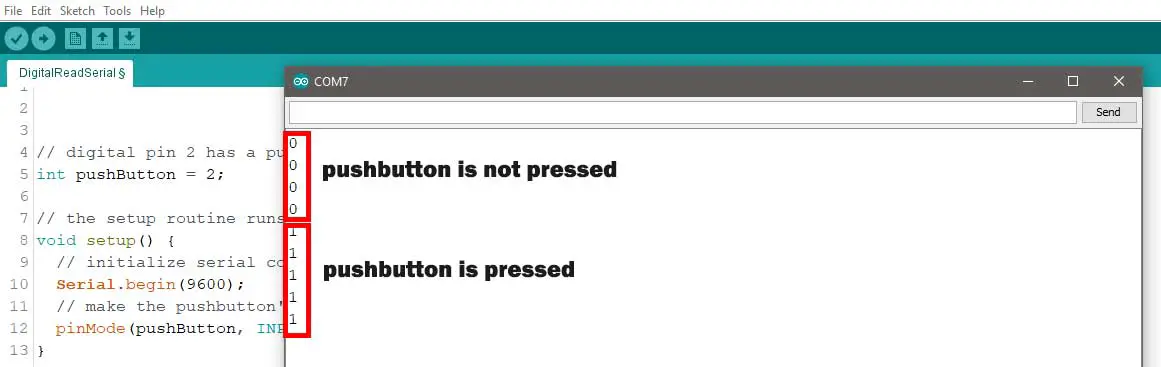
val= digitalRead(PinButton1);The first statement in the loop function reads: val=digitalRead(pinbutton1); This means we are now asking Arduino for the current state of the pushbutton. Is it pressed? Is it not pressed? Arduino will give us an answer, 1 for pressed and 0 for not pressed. Well, this actually depends on how the resistor was used (pull-up or pull-down).
Serial.println(val);Now that we have the answer, what’s left for us to do is to display the answer on the screen. To do this we type in Serial.println(val). When this is executed, the word val is not displayed but the value of the val variable will be displayed, which is 1 or 0.
We then write a delay statement to tell Arduino when the next reading will take place. In this case, the pushbutton is read every 100 milliseconds. In addition, the value of the variable val will be displayed every 100 milliseconds on the screen.
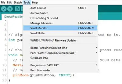
To view the pushbutton readings on the screen, you have to upload the code first. Once the code is uploaded successfully, we then go to the Tools menu then click on Serial Monitor. A new window will open showing the values being read from the pushbuttons.
PROJECT 2: Switch On Switch Off
Switching Lights Using the Pushbutton
Now that we know how to read the value of a pushbutton, we’ll use this for our next project, Project 9, which is Switch On Switch Off. What we want to do here is to turn on the LED when the pushbutton is pressed, and turn it off, when it is released.
For the circuit, we’ll just need to add an LED to our breadboard, which should be fairly automatic by now. In this circuit, we connect the anode to digital pin 10.
On to the code. We declare the variables again for the pushbutton and the LED. We also need to declare a variable where the value of the pushbutton will be saved for later use. This is the variable named val. Here is the code:
  /*
    1.  When the button is pressed,
      turn on the LED
    2.  When the button is released,
      turn off the LED
  */

  int PinButton1 = 2;
  int PinLed = 10;
  int val =0;

  void setup()
  {
    pinMode(PinButton1, INPUT);
    pinMode(PinLed, OUTPUT);
  }

  void loop()
  {
    val=digitalRead(PinButton1);

    if(val == HIGH) //button is pressed
    {
      digitalWrite(PinLed, HIGH);
    }
    else //button is released
    {
      digitalWrite(PinLed, LOW);
    }
  }
In the setup function, we set the PinButton1 variable as input while the PinLed variable is set to OUTPUT. Again, since we already added the 10k ohm resistor, there’s no need to type in the digitalWrite(PinButton1 , HIGH) statement (as seen on the Arduino Intro app).
Let’s go to the main loop function. I have made a slight modification to this code to make it clearer.
In this code, you will need to know about the if statement. The if statement is possibly the most important instruction in a programming language because it allows a computer or in this case the Arduino to make decisions. After the if keyword, you have to write a conditional statement inside parentheses. Think of the conditional statement as a question you want to ask from Arduino, and if the “answer”, or result, is true, the first block of code will be executed; otherwise, the block of code after else will be executed.
val=digitalRead(PinButton1);Ok so the first statement here is to read the value of our pushbutton, so we typed val=digitalRead(PinButton1 ). We should get a 1 or 0. In Arduino, a 1 value is the same as HIGH, and a 0 value is the same as LOW. So if we get a 1, that means the pushbutton is pressed. If we get a 0, it means that the pushbutton is released.
if(val == HIGH) //button is pressed
    {
      digitalWrite(PinLed, HIGH);
    }
    else //button is released
    {
      digitalWrite(PinLed, LOW);
    }
After getting the value of our pushbutton, we then write the if statement. What we want to do is if the button is pressed, turn on the LED, else, turn off the LED. Converting this statement into an if statement is easy. We just type in if (val==HIGH){ digitalWrite(PinLed, HIGH);} else {digitalWrite(PinLed,LOW);}
Notice that the == symbol is very different from the = symbol. The double equal sign is used when two expressions are compared, and returns true or false; the single equal sign assigns a value to a constant or a variable. Make sure that you use the correct one because it is very easy to make that mistake and use just a single equal sign instead of a double, in which case your program will never work.
PROJECT 3: "Sticky" Switch
Making the "Sticky" Pushbutton
This project is already good as it is, however, we can still improve this one. Right now, holding your finger on the button for as long as you need light is not practical. We need a way to let the button stick to its current state. Like pushing the button once, turns on the LED. And pushing it again turns the LED off.
For this to happen, we’ll need the same breadboard circuit but we need to tweak our code a little bit. It’s really a simple code but very effective. What we need is another variable to save the value of HIGH or LOW. Every time we push the button, we change the value of this variable. For example, if the current value of this variable is HIGH, then we’ll change it to LOW. If it is LOW, then we’ll change it to HIGH. Finally, when we type a digitalWrite statement, we can then use this variable to turn the led on or off.
So how is this translated into code? Here's the final code for our "sticky" pushbutton:
  /*
  The "sticky" push button
  LED turns on when pushbutton is pressed and released once.
  LED stays ON
  LED turns off when pushbutton is pressed again.
  LED stays OFF
  */

  int PinButton1 = 2;
  int PinLed = 10;
  int val =0;
  int ledstate=LOW; //initial value

  void setup()
  {
    pinMode(PinButton1, INPUT);
    pinMode(PinLed, OUTPUT);
  }

  void loop()
  {
    val=digitalRead(PinButton1);

    if(val == HIGH) //button is pressed
    {
      //reverse the current state of the ledstate variable
      ledstate=!ledstate;
      digitalWrite(PinLed, ledstate);
      //wait 1 second before the next reading to ensure stability
      delay(1000);
    }

  }
First, we add this variable that will hold the HIGH or LOW value. Let’s name it as ledstate and give it an initial value of LOW. Then in the condition where the button is pressed (which is if (val ==1)), we add the line ledstate=!ledstate;
ledstate=!ledstate;This is read as ledstate is equal to not ledstate. You may want to let that thought sink in for a second. The exclamation mark in Arduino means NOT. This is really where the magic comes in. We can also interpret it as let the new value of the ledstate variable be not the current value of the ledstate variable. Therefore, if the current value of ledstate is LOW, then the new value of the ledstate variable is HIGH, which is not LOW. Sounds confusing at first but logically it makes sense.
digitalWrite(PinLed, ledstate);Finally, in the digitalWrite function, we simply say digitalWrite(PinLed, ledstate). When the program is run, the variable ledstate will be replaced by the actual value of ledstate (HIGH or LOW). A delay of 1 second is added in preparation for the next reading.
In this article, we talked about getting input from a pushbutton to turn on and turn off an LED. This is really what makes Arduino so exciting, being able to read what’s happening in the physical world and having the ability to react. If this is all new to you, you may want to try this project now.


