If you’re new to Arduino and looking for a project that’s both fun and practical, learning to use a 7-segment display is an excellent starting point. A 7-segment display is a simple electronic component commonly used in devices like clocks, calculators, and counters to display numerical data. By the end of this guide, you’ll know how to control a 7-segment display with Arduino, write the necessary code, and apply your new knowledge to real-world projects like digital clocks or scoreboards.
What Is a 7-Segment Display?
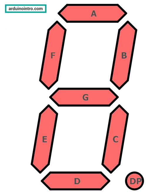
A 7-segment display is a rectangular display component divided into seven individual segments arranged in a figure-eight pattern. By selectively illuminating these segments, you can display numbers from 0 to 9 and some simple alphabetic characters. The display can be either common anode or common cathode, depending on how the segments are powered.
Why Use a 7-Segment Display with Arduino?
7-segment displays are commonly used in projects like:
- Digital clocks
- Thermometers
- Countdown timers
- Scoreboards
These applications make it a practical choice for beginners learning Arduino and electronics. Plus, it’s an excellent way to practice controlling multiple outputs with your microcontroller.
What You’ll Need
Here’s a list of materials for this project:
- An Arduino board (e.g., Arduino Uno)
- A common cathode or common anode 7-segment display
- 8 x 220-ohm resistors
- Jumper wires
- A breadboard
- USB cable and Arduino IDE installed on your computer
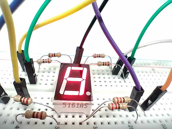
Note: For this tutorial, we will use the 5161AS, a common cathode 7-segment display.
Step-by-Step Guide to Using a 7-Segment Display with Arduino
Step 1: Understanding the Pins of a 7-Segment Display
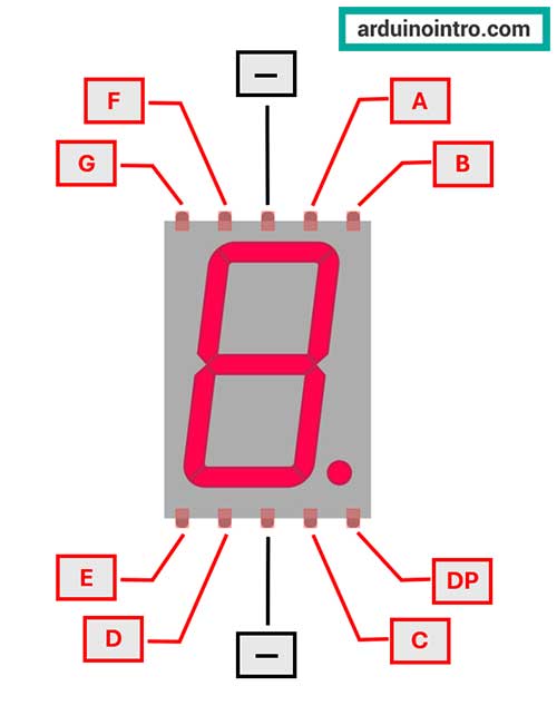
Each segment of a 7-segment display is an LED. The display has 10 pins:
- a, b, c, d, e, f, g: Control the seven LED segments.
- DP: Controls the decimal point.
- Common Cathode (CC) or Common Anode (CA): Determines the display type.
In a common cathode display, all cathode (negative) pins are connected together. In a common anode display, all anode (positive) pins are connected.
Step 2: Connecting the 7-Segment Display to Arduino
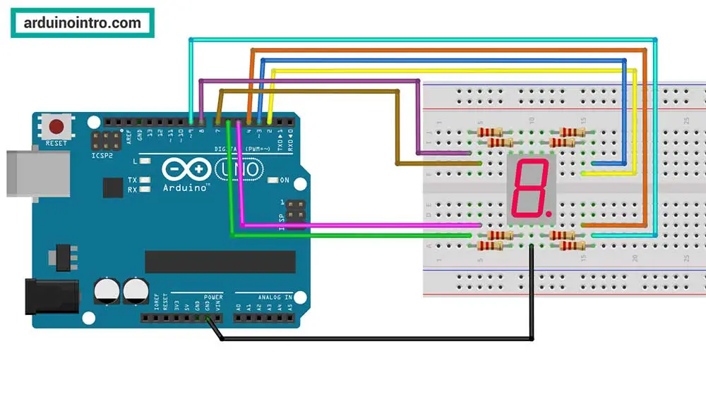
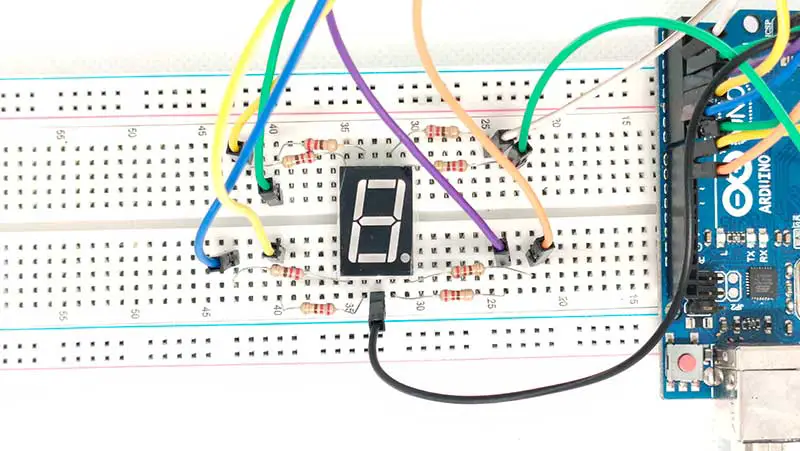
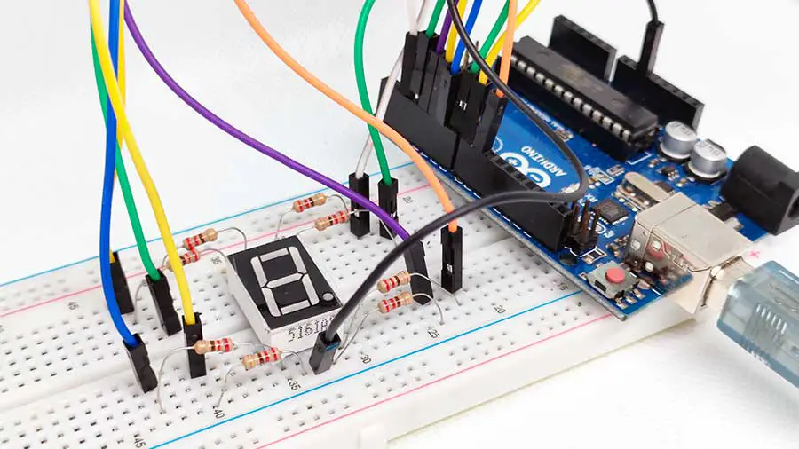
Here’s how to wire a common cathode 7-segment display:
- Place the display on the breadboard.
- Connect each segment (a through g and DP) to digital pins on the Arduino via 220-ohm resistors.
- Connect the common cathode pin to the GND pin of the Arduino.
- Here’s an example wiring:
| Segment | Arduino Pin |
|---|---|
| a | 2 |
| b | 3 |
| c | 4 |
| d | 5 |
| e | 6 |
| f | 7 |
| g | 8 |
| DP | 9 |
Arduino Code for 7-Segment Display
Below is a simple Arduino sketch to display the number “8” on a 7-segment display.
// Define segment pins
const int segmentPins[] = {2, 3, 4, 5, 6, 7, 8};

// Segment states for numbers 0-9
const int digits[10][7] = {
  {1, 1, 1, 1, 1, 1, 0}, // 0
  {0, 1, 1, 0, 0, 0, 0}, // 1
  {1, 1, 0, 1, 1, 0, 1}, // 2
  {1, 1, 1, 1, 0, 0, 1}, // 3
  {0, 1, 1, 0, 0, 1, 1}, // 4
  {1, 0, 1, 1, 0, 1, 1}, // 5
  {1, 0, 1, 1, 1, 1, 1}, // 6
  {1, 1, 1, 0, 0, 0, 0}, // 7
  {1, 1, 1, 1, 1, 1, 1}, // 8
  {1, 1, 1, 1, 0, 1, 1}  // 9
};

void setup() {
  // Set segment pins as output
  for (int i = 0; i < 7; i++) {
    pinMode(segmentPins[i], OUTPUT);
  }
}

void loop() {
  // Display the number 8
  displayDigit(8);
  delay(1000); // Wait for 1 second
}

void displayDigit(int number) {
  for (int i = 0; i < 7; i++) {
    digitalWrite(segmentPins[i], digits[number][i]);
  }
}
Code Breakdown
1. Define Segment Pins
const int segmentPins[] = {2, 3, 4, 5, 6, 7, 8};
- What this does:
This array defines the Arduino digital pins (2 to 8) that are connected to the seven segments of the 7-segment display (a, b, c, d, e, f, g). - Why it matters:
Each pin corresponds to one segment of the display, allowing you to individually control whether each segment is on or off.
2. Define Segment States for Numbers 0-9
const int digits[10][7] = {
  {1, 1, 1, 1, 1, 1, 0}, // 0
  {0, 1, 1, 0, 0, 0, 0}, // 1
  {1, 1, 0, 1, 1, 0, 1}, // 2
  {1, 1, 1, 1, 0, 0, 1}, // 3
  {0, 1, 1, 0, 0, 1, 1}, // 4
  {1, 0, 1, 1, 0, 1, 1}, // 5
  {1, 0, 1, 1, 1, 1, 1}, // 6
  {1, 1, 1, 0, 0, 0, 0}, // 7
  {1, 1, 1, 1, 1, 1, 1}, // 8
  {1, 1, 1, 1, 0, 1, 1}  // 9
};
- What this does:
This 2D array defines which segments should be lit (1) or turned off (0) to display the digits 0 through 9. - Why it matters:
The first sub-array corresponds to the digit0, the second to1, and so on. Each array element corresponds to a segment of the display (atog).
3. Setup Function
void setup() {
  // Set segment pins as output
  for (int i = 0; i < 7; i++) {
    pinMode(segmentPins[i], OUTPUT);
  }
}
- What this does:
This function runs once when the Arduino is powered on or reset. It configures the seven segment pins (2 to 8) as output using thepinMode()function. - Why it matters:
Configuring the pins as outputs is necessary to control the voltage sent to the segments.
4. Loop Function
void loop() {
  // Display the number 8
  displayDigit(8);
  delay(1000); // Wait for 1 second
}
- What this does:
Theloop()function continuously calls thedisplayDigit()function to display the number8on the 7-segment display. After displaying the number, it waits for 1 second (delay(1000)). - Why it matters:
This is the main loop of the program, which updates the display and provides a delay to keep the number visible.
5. Display Digit Function
void displayDigit(int number) {
  for (int i = 0; i < 7; i++) {
    digitalWrite(segmentPins[i], digits[number][i]);
  }
}
- What this does:
This custom function lights up the appropriate segments to display the specified number.- The
forloop goes through each of the seven segment pins (segmentPins[i]). - The
digitalWrite()function sets the state of each pin to either HIGH (1) or LOW (0) based on thedigitsarray for the specified number.
- The
- Why it matters:
This function makes the code modular and reusable. Instead of writing the logic for each digit separately, this function handles all digits dynamically.
How the Code Works Together
- In the
setup()function, the Arduino pins connected to the 7-segment display are set as outputs. - In the
loop()function, the number8is displayed by callingdisplayDigit(8). - Inside the
displayDigit()function, the corresponding segments for8are turned on by setting the appropriate pins to HIGH (1) and the rest to LOW (0). - After displaying the digit, the
delay(1000)pauses the execution for 1 second.
Practical Example
You can modify the loop() function to cycle through numbers 0–9, displaying each digit for one second:
void loop() {
  for (int i = 0; i < 10; i++) {
    displayDigit(i);
    delay(1000); // Wait for 1 second
  }
}
This modification creates a basic counter, showing the versatility of the displayDigit() function.
Here's my demonstration:
Arduino Code with Decimal Point Control
To control the decimal point (DP) on a 7-segment display, you need to connect the DP pin of the display to an Arduino pin. This pin works like any other segment pin, so you can turn the decimal point on or off using digitalWrite().
Here's an updated code snippet incorporating the DP functionality:
// Define segment pins (a, b, c, d, e, f, g, DP)
const int segmentPins[] = {2, 3, 4, 5, 6, 7, 8, 9}; // Added pin 9 for the DP

// Segment states for numbers 0-9
const int digits[10][7] = {
  {1, 1, 1, 1, 1, 1, 0}, // 0
  {0, 1, 1, 0, 0, 0, 0}, // 1
  {1, 1, 0, 1, 1, 0, 1}, // 2
  {1, 1, 1, 1, 0, 0, 1}, // 3
  {0, 1, 1, 0, 0, 1, 1}, // 4
  {1, 0, 1, 1, 0, 1, 1}, // 5
  {1, 0, 1, 1, 1, 1, 1}, // 6
  {1, 1, 1, 0, 0, 0, 0}, // 7
  {1, 1, 1, 1, 1, 1, 1}, // 8
  {1, 1, 1, 1, 0, 1, 1}  // 9
};

void setup() {
  // Set all segment pins as output
  for (int i = 0; i < 8; i++) { // Include the DP pin (index 7)
    pinMode(segmentPins[i], OUTPUT);
  }
}

void loop() {
  // Display the number 3 with the decimal point ON
  displayDigit(3, true);
  delay(1000); // Wait for 1 second

  // Display the number 7 with the decimal point OFF
  displayDigit(7, false);
  delay(1000); // Wait for 1 second
}

// Function to display a digit and control the decimal point
void displayDigit(int number, bool dpState) {
  for (int i = 0; i < 7; i++) {
    digitalWrite(segmentPins[i], digits[number][i]);
  }

  // Control the decimal point
  digitalWrite(segmentPins[7], dpState ? HIGH : LOW); // DP is at index 7
}
Explanation of Changes
-
Added DP Pin:
segmentPins[]now includes an additional pin (pin 9) for the decimal point.
-
displayDigit()Function Update:- The function now accepts an additional parameter,
dpState(a boolean), which determines whether the decimal point is ON (true) or OFF (false). - The decimal point pin (
segmentPins[7]) is controlled separately usingdigitalWrite().
- The function now accepts an additional parameter,
-
Usage in
loop():- The number
3is displayed with the decimal point ON, followed by the number7with the decimal point OFF.
- The number
FAQs About 7-Segment Displays
Q: Can I use multiple 7-segment displays with Arduino? Yes, you can! To control multiple displays, you’ll need additional components like shift registers or multiplexers to manage the number of pins required.
Q: What’s the difference between common anode and common cathode displays? In a common cathode display, all cathodes are connected to GND, and segments light up with a HIGH signal. In a common anode display, all anodes are connected to 5V, and segments light up with a LOW signal.
Q: How can I reduce the number of pins used by the display? You can use a driver IC like the 74HC595 shift register or the MAX7219 to control the 7-segment display with fewer pins.
Conclusion
Learning how to use a 7-segment display with Arduino opens doors to a variety of exciting projects. With just a few components, you can build functional displays for numerical data. We hope this guide has been a helpful resource for getting started.


Is there a project in which 4 inputs read binair and display to a screen 0-9,A,B,C,D,E,F
On crystal screen ?
Thank you
Ro