Are you looking to add precise timekeeping to your Arduino projects? Whether you're creating a home automation system, a data logger, or any project that requires accurate time tracking, the DS1307 Real Time Clock (RTC) module is an excellent choice.
In this article, we will dive deep into using the DS1307 RTC module with Arduino, provide a step-by-step guide, and offer a comparison between the DS1307 and DS1302 RTC modules. This guide is designed for beginners and will help you get your projects up and running in no time.
Why Use an RTC Module in Your Arduino Projects?
An RTC module, like the DS1307, allows your Arduino to keep track of the time even when it's powered off. This is crucial for applications such as:
- Data Logging: Record timestamps with your sensor readings.
- Home Automation: Schedule tasks like turning lights on and off.
- Alarm Systems: Trigger alarms at specific times.
Key Features of the DS1307 RTC Module
- Battery Backup: Keeps track of time even during power outages.
- I2C Communication: Simple two-wire interface for easy connection with Arduino.
- Timekeeping: Provides seconds, minutes, hours, day, date, month, and year information.
Comparing DS1307 and DS1302 RTC Modules
When selecting an RTC module for your project, you might come across the DS1302. Here's a comparison between the DS1307 and DS1302 to help you decide which one to use.
| Feature | DS1307 RTC Module | DS1302 RTC Module |
| Communication | I2C (2-wire) | SPI (3-wire) |
| Voltage | 5V | 2V to 5.5V |
| Battery Backup | Yes | Yes, with a separate pin for battery input |
| Timekeeping | Seconds, minutes, hours, day, date, month, year | Seconds, minutes, hours, day, date, month, year, and supports leap year compensation up to 2100 |
| Communication Protocol | Simpler (I2C requires fewer wires) | More complex (SPI requires more wires) |
| Voltage Range | Narrower | Broader, more versatile |
| Battery Backup Pin | No dedicated pin | Dedicated pin for battery input |
Key Differences
- Communication Protocol: The DS1307 uses I2C, which is simpler and requires fewer wires compared to the DS1302's SPI.
- Voltage Range: The DS1302 has a broader voltage range, making it more versatile in different projects.
- Battery Backup: Both modules offer battery backup, but the DS1302 provides a dedicated pin for battery input, which might be beneficial for certain designs.
Getting Started with DS1307 RTC Module and Arduino
Components Needed
- Arduino Board (e.g., Arduino Uno)
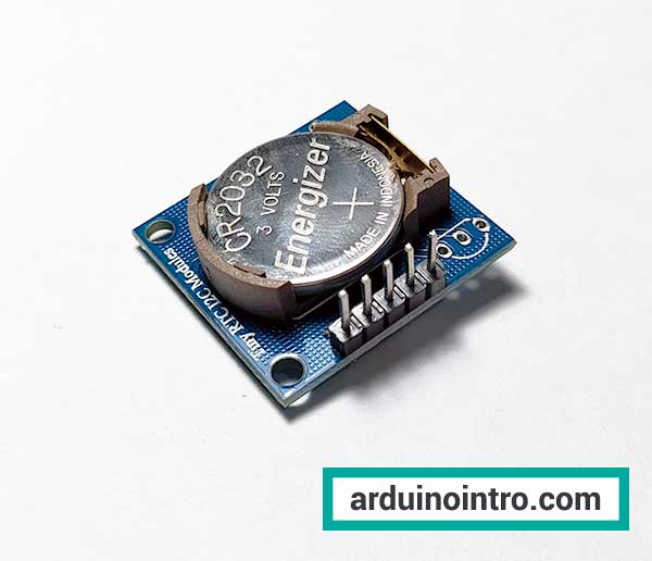
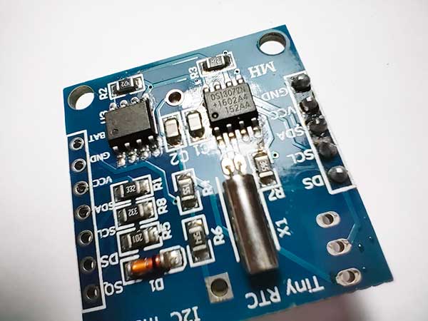
- DS1307 RTC Module
- Breadboard and Jumper Wires
- 3V Lithium Coin Cell Battery (for RTC module backup)
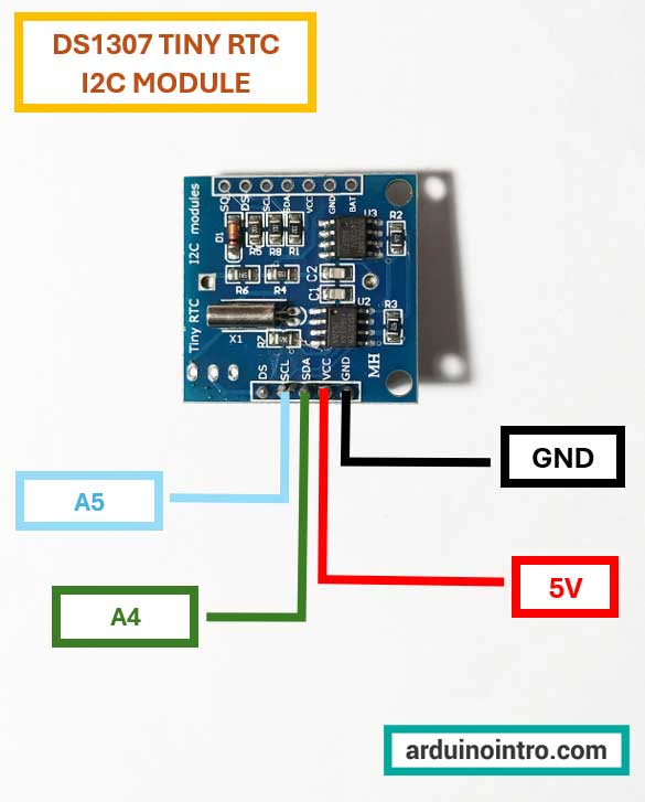
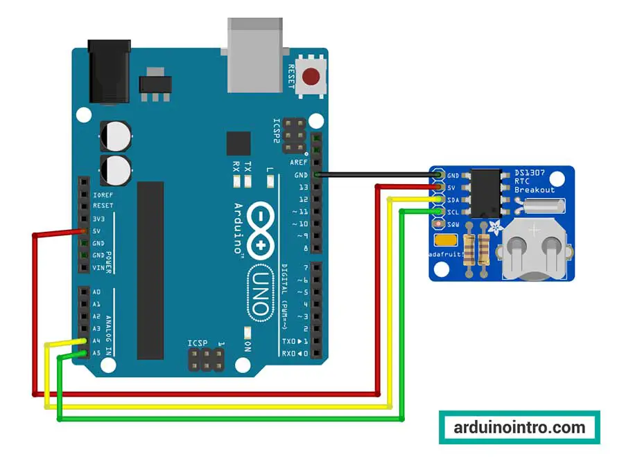
Circuit Diagram
To connect the DS1307 RTC module to the Arduino, follow the circuit diagram below:
DS1307 RTC Module |
Arduino |
| VCC | 5V |
| GND | GND |
| SDA | A4 |
| SCL | A5 |
Installing the Required Libraries
Before we start coding, we need to install the necessary libraries. Download the DS1307 library here:
To install the library:
Open the Arduino IDE and go to Sketch > Include Library > Add .ZIP Library. Search for the downloaded library and click OK.
Arduino Code for DS1307 RTC Module
Here's a basic example code to get you started with the DS1307 RTC module.
#include "DS1307.h"

DS1307 clock;//define a object of DS1307 class

void setup() {
    Serial.begin(9600);
    clock.begin();

    //uncomment the next 4 lines to set a new date and time, then upload
    //clock.fillByYMD(2024, 6, 25); //June 25,2024 (year, month, date)
    //clock.fillByHMS(13, 55, 30); //1:55 PM 30 13:55:30 (hh:mm:ss)24 hr format
    //clock.fillDayOfWeek(TUE);//Tuesday
    //clock.setTime();//write time to the RTC chip

    //comment the 4 lines again then upload so that the date and time will not be reset
}
void loop() {
    clock.getTime();
    Serial.print(clock.hour, DEC);
    Serial.print(":");
    Serial.print(clock.minute, DEC);
    Serial.print(":");
    Serial.print(clock.second, DEC);
    Serial.print("  ");
    Serial.print(clock.month, DEC);
    Serial.print("/");
    Serial.print(clock.dayOfMonth, DEC);
    Serial.print("/");
    Serial.print(clock.year + 2000, DEC);
    Serial.println();

    delay(1000);

}
This should be the output once you upload the code and open the Serial Monitor:
Step-by-Step Explanation of the Code
Including the Library and Creating an Object
#include "DS1307.h"

DS1307 clock; // Define an object of DS1307 class
#include "DS1307.h": This line includes the DS1307 library, which contains the necessary functions and definitions for interacting with the DS1307 RTC module.DS1307 clock;: This line creates an instance of the DS1307 class namedclock. This object will be used to call the functions provided by the library to interact with the RTC module.
Setup Function
void setup() {
    Serial.begin(9600);
    clock.begin();

    // Uncomment the next 4 lines to set a new date and time, then upload
    // clock.fillByYMD(2024, 6, 25); // June 25, 2024 (year, month, date)
    // clock.fillByHMS(13, 55, 30); // 1:55 PM (13:55:30) in 24-hour format
    // clock.fillDayOfWeek(TUE); // Tuesday
    // clock.setTime(); // Write time to the RTC chip

    // Comment the 4 lines again then upload so that the date and time will not be reset
}
Serial.begin(9600);: Initializes the serial communication at a baud rate of 9600 bits per second. This is used for communication between the Arduino and the computer.clock.begin();: Initializes the RTC module. It sets up the communication between the Arduino and the DS1307 RTC module.
The following lines are commented out. If you want to set the time and date on the RTC module, you need to uncomment these lines, upload the sketch to the Arduino, and then comment them out again before uploading the sketch a second time:
clock.fillByYMD(2024, 6, 25);: Sets the year, month, and day (June 25, 2024).clock.fillByHMS(13, 55, 30);: Sets the hour, minute, and second (13:55:30 in 24-hour format).clock.fillDayOfWeek(TUE);: Sets the day of the week to Tuesday.clock.setTime();: Writes the set time and date to the RTC module.
Loop Function
void loop() {
    clock.getTime();
    Serial.print(clock.hour, DEC);
    Serial.print(":");
    Serial.print(clock.minute, DEC);
    Serial.print(":");
    Serial.print(clock.second, DEC);
    Serial.print("  ");
    Serial.print(clock.month, DEC);
    Serial.print("/");
    Serial.print(clock.dayOfMonth, DEC);
    Serial.print("/");
    Serial.print(clock.year + 2000, DEC);
    Serial.println();

    delay(1000);
}
clock.getTime();: Retrieves the current time from the RTC module and updates the properties of theclockobject with the current hour, minute, second, day, month, and year.Serial.print(clock.hour, DEC);: Prints the current hour to the serial monitor.Serial.print(":");: Prints a colon (:) to separate the hour and minute.Serial.print(clock.minute, DEC);: Prints the current minute to the serial monitor.Serial.print(":");: Prints a colon (:) to separate the minute and second.Serial.print(clock.second, DEC);: Prints the current second to the serial monitor.Serial.print(" ");: Prints two spaces to separate the time from the date.Serial.print(clock.month, DEC);: Prints the current month to the serial monitor.Serial.print("/");: Prints a forward slash (/) to separate the month and day.Serial.print(clock.dayOfMonth, DEC);: Prints the current day of the month to the serial monitor.Serial.print("/");: Prints a forward slash (/) to separate the day and year.Serial.print(clock.year + 2000, DEC);: Prints the current year to the serial monitor. Theclock.yearvalue is offset by 2000 because the DS1307 typically returns the year as a number from 0 to 99 (representing 2000 to 2099).Serial.println();: Prints a newline character, moving the cursor to the next line on the serial monitor.delay(1000);: Pauses the loop for 1000 milliseconds (1 second) before repeating, resulting in the time being updated every second.
Code Summary
This code sets up an Arduino to interact with a DS1307 RTC module, allowing it to keep track of and display the current time and date via the serial monitor. Initially, you can set the time and date by uncommenting certain lines, uploading the code, and then commenting them out and re-uploading to ensure the time isn't reset each time the Arduino restarts. The loop function continually retrieves and displays the current time and date every second.
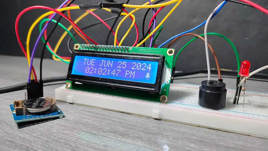
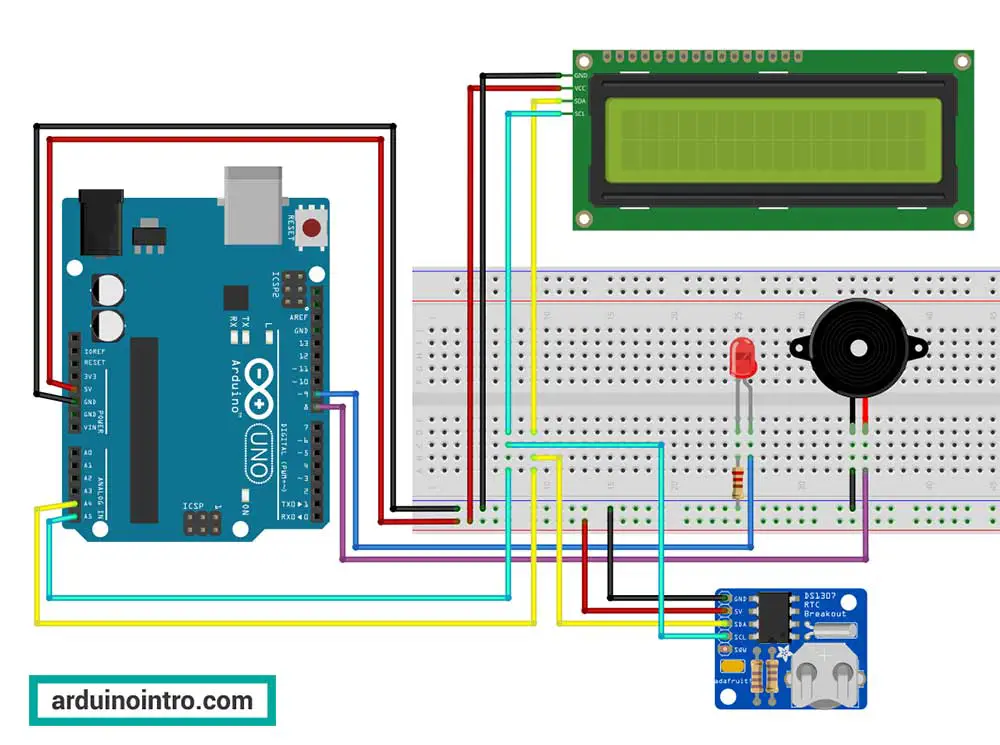
Practical Application: Creating a Simple Alarm Clock
Let's take the DS1307 RTC module and build a simple alarm clock. You can add a buzzer, LED, and an LCD display to show the current time and trigger the alarm at a set time. Here's an extended code snippet to incorporate an alarm feature:
Components Needed:
- Arduino Uno
- DS1307 RTC Module
- 16x2 Liquid Crystal Display (LCD)
- Buzzer
- Breadboard
- Jumper wires
- LED
- 220-ohm resistor for the LED
This is the complete breadboard circuit:
Learn more about I2C LCD
|
|
For detailed knowledge about I2C LCD, read this article: Displaying Characters Using the I2C Liquid Crystal Display (LCD) (This link opens in another window) |
Learn more about Piezo Buzzer
|
|
Get more information on Piezo Buzzer in this article: Exploring Piezo Buzzer Integration with Arduino: A Comprehensive Guide (This link opens in another window) |
Arduino Code for DS1307 RTC Module with Alarm Function
Here is the code for this application:
#include <Wire.h>
#include "DS1307.h"
#include <LiquidCrystal_I2C.h> //enables us to use the lcd functions

int buzzer = 8; // Pin for the buzzer
int led=9;
int ampm;
int hourNow=0;
int minuteNow=0;
int alarmHour =14; //set alarm at 2:00 PM
int alarmMinute =0;

LiquidCrystal_I2C lcd(0x27, 2, 1, 0, 4, 5, 6, 7, 3, POSITIVE);
DS1307 clock;//define a object of DS1307 class

// Make a custom bell character:

byte Bell[] = {
  B00100,
  B01110,
  B01110,
  B01110,
  B11111,
  B00000,
  B00100,
  B00000
};

void setup() {
    //Serial.begin(9600);
    lcd.begin(16,2);
    pinMode(buzzer,OUTPUT);
    pinMode(led,OUTPUT);
    clock.begin();

    //uncomment the next 4 lines to set a new date and time, then upload
    //clock.fillByYMD(2024, 6, 25); //June 25,2024 (year, month, date)
    //clock.fillByHMS(13, 55, 30); //1:55 PM 30 13:55:30 (hh:mm:ss)24-hr format
    //clock.fillDayOfWeek(TUE);//Tuesday
    //clock.setTime();//write time to the RTC chip

    //comment the 4 lines again then upload so that the date and time will not be reset

    // Create new character:
    lcd.createChar(0, Bell);

}

void loop() {

 lcd.clear();//Clear the lcd screen
 clock.getTime();

 //Name of the day
 String s_day;
 switch (clock.dayOfWeek) { // Friendly printout the weekday
     case MON:
         s_day="MON";
         break;
     case TUE:
         s_day="TUE";
         break;
     case WED:
         s_day="WED";
         break;
     case THU:
         s_day="THU";
         break;
     case FRI:
         s_day="FRI";
         break;
     case SAT:
         s_day="SAT";
         break;
     case SUN:
         s_day="SUN";
         break;
    }


  //Name of the month
  String s_month;
  switch (clock.month)
  {
    case 1:
      s_month="JAN ";
      break;
    case 2:
      s_month="FEB ";
      break;
    case 3:
      s_month="MAR ";
      break;
    case 4:
      s_month="APR ";
      break;
    case 5:
      s_month="MAY ";
      break;
    case 6:
      s_month="JUN ";
      break;
    case 7:
      s_month="JUL ";
      break;
    case 8:
      s_month="AUG ";
      break;
    case 9:
      s_month="SEP ";
      break;
    case 10:
      s_month="OCT ";
      break;
    case 11:
      s_month="NOV ";
      break;
    case 12:
      s_month="DEC ";
      break;
  }

    //alarm
    hourNow=clock.hour;
    minuteNow=clock.minute;
    if (hourNow == alarmHour && minuteNow == alarmMinute) {
      tone(buzzer,1300);
      digitalWrite(led, HIGH);
    } else {
      noTone(buzzer);
      digitalWrite(led, LOW);
    }


  //display date
  lcd.setCursor(1,0);
  lcd.print(s_day);
  lcd.print(" ");
  lcd.print(s_month);

  if (clock.dayOfMonth<=9){
      lcd.print("0");
      lcd.print(clock.dayOfMonth,DEC);
    }
  else{
    lcd.print(clock.dayOfMonth, DEC);
  }

  lcd.print(" ");
  lcd.print(clock.year + 2000);


  // display time
  lcd.setCursor(2,1);


  //Time AM/PM
  if (clock.hour>=12){
    ampm = 1;
    clock.hour = clock.hour-12;
     if (clock.hour== 0) {
        clock.hour = 12; // Day 12 PM
     }
  if (clock.hour<=9){
    lcd.print("0");
    lcd.print(clock.hour);
    lcd.print(":");
  }
  else {
    lcd.print(clock.hour);
    lcd.print(":");}
  }
  else {
    ampm = 0;
    if(clock.hour==0){
      clock.hour=12; // Night 12 AM
    }
    if (clock.hour<=9){
      lcd.print("0");
      lcd.print(clock.hour);
      lcd.print(":");
    }
    else {
      lcd.print(clock.hour);
      lcd.print(":");}
    }
    if (clock.minute<=9){
      lcd.print("0");
      lcd.print(clock.minute);
      lcd.print(":");
    }
    else {
      lcd.print(clock.minute);
      lcd.print(":");}
    if (clock.second<=9){
      lcd.print("0");
      lcd.print(clock.second);
      lcd.print(" ");
    }
    else {
      lcd.print(clock.second);
      lcd.print(" ");
    }

    //AM/PM
    if (ampm==1){
      lcd.print("PM");
    }else{
      lcd.print("AM"); }


    //display bell character
    lcd.setCursor(15, 1);
    lcd.write(byte(0));


delay(1000);
}
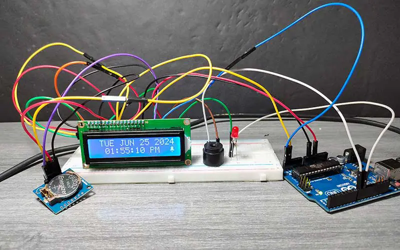
This is my demonstration of this application:
Step-by-Step Explanation of the Code
Here's a step-by-step explanation of the provided Arduino code that uses the DS1307 RTC module and an I2C LCD display to create an alarm clock with a buzzer and LED:
Including Libraries and Defining Objects
#include <Wire.h>
#include "DS1307.h"
#include <LiquidCrystal_I2C.h> // Enables us to use the LCD functions

int buzzer = 8; // Pin for the buzzer
int led = 9; // Pin for the LED
int ampm;
int hourNow = 0;
int minuteNow = 0;
int alarmHour = 14; // Set alarm at 2:00 PM
int alarmMinute = 0;

LiquidCrystal_I2C lcd(0x27, 2, 1, 0, 4, 5, 6, 7, 3, POSITIVE);
DS1307 clock; // Define an object of DS1307 class

// Make a custom bell character
byte Bell[] = {
  B00100,
  B01110,
  B01110,
  B01110,
  B11111,
  B00000,
  B00100,
  B00000
};
#include <Wire.h>: Includes the Wire library for I2C communication.#include "DS1307.h": Includes the DS1307 library for RTC functions.#include <LiquidCrystal_I2C.h>: Includes the LiquidCrystal_I2C library for using I2C LCD functions.- Variable Declarations: Defines pins for the buzzer and LED, as well as variables for handling the time and alarm.
LiquidCrystal_I2C lcd(...);: Creates an object for the I2C LCD with specified address and pin configuration.DS1307 clock;: Creates an object for the DS1307 RTC module.- Custom Bell Character: Defines a custom bell character for the LCD.
You may download all the required libraries at the end of this article.
Setup Function
void setup() {
    // Serial.begin(9600);
    lcd.begin(16, 2);
    pinMode(buzzer, OUTPUT);
    pinMode(led, OUTPUT);
    clock.begin();

    // Uncomment the next 4 lines to set a new date and time, then upload
    // clock.fillByYMD(2024, 6, 25); // June 25, 2024 (year, month, date)
    // clock.fillByHMS(13, 55, 30); // 1:55 PM (13:55:30) in 24-hr format
    // clock.fillDayOfWeek(TUE); // Tuesday
    // clock.setTime(); // Write time to the RTC chip

    // Comment the 4 lines again then upload so that the date and time will not be reset

    // Create new character
    lcd.createChar(0, Bell);
}
lcd.begin(16, 2);: Initializes the LCD with 16 columns and 2 rows.pinMode(buzzer, OUTPUT);andpinMode(led, OUTPUT);: Sets the buzzer and LED pins as output.clock.begin();: Initializes the RTC module.- Setting Time (Commented Out): Provides code to set the time on the RTC module, which should be uncommented, uploaded, then commented again.
lcd.createChar(0, Bell);: Creates a custom character (bell) for the LCD.
Loop Function
This function runs repeatedly after the setup() function is executed. Its main tasks are to update the LCD display with the current date and time, check for an alarm condition, and sound a buzzer and light an LED if the alarm time is reached.
Here's a step-by-step explanation:
Clear the LCD Screen
lcd.clear(); // Clear the LCD screen
This line clears any previous content on the LCD screen.
Get the Current Time from the RTC
clock.getTime();
This method retrieves the current time from the DS1307 RTC module and updates the clock object with the new time.
Get the Day of the Week
String s_day;
switch (clock.dayOfWeek) { // Friendly printout of the weekday
    case MON: s_day = "MON"; break;
    case TUE: s_day = "TUE"; break;
    case WED: s_day = "WED"; break;
    case THU: s_day = "THU"; break;
    case FRI: s_day = "FRI"; break;
    case SAT: s_day = "SAT"; break;
    case SUN: s_day = "SUN"; break;
}
This block converts the numerical value of clock.dayOfWeek to a string representing the name of the day (e.g., MON, TUE).
Get the Month
String s_month;
switch (clock.month) {
    case 1: s_month = "JAN "; break;
    case 2: s_month = "FEB "; break;
    case 3: s_month = "MAR "; break;
    case 4: s_month = "APR "; break;
    case 5: s_month = "MAY "; break;
    case 6: s_month = "JUN "; break;
    case 7: s_month = "JUL "; break;
    case 8: s_month = "AUG "; break;
    case 9: s_month = "SEP "; break;
    case 10: s_month = "OCT "; break;
    case 11: s_month = "NOV "; break;
    case 12: s_month = "DEC "; break;
}
This block converts the numerical value of clock.month to a string representing the name of the month (e.g., JAN, FEB).
Check and Handle Alarm Condition
hourNow = clock.hour;
minuteNow = clock.minute;
if (hourNow == alarmHour && minuteNow == alarmMinute) {
    tone(buzzer, 1300);
    digitalWrite(led, HIGH);
} else {
    noTone(buzzer);
    digitalWrite(led, LOW);
}
hourNowandminuteNowstore the current hour and minute.- If the current time matches the alarm time (
alarmHourandalarmMinute), the buzzer sounds, and the LED turns on. - Otherwise, the buzzer and LED are turned off.
Display the Date
lcd.setCursor(1, 0);
lcd.print(s_day);
lcd.print(" ");
lcd.print(s_month);
if (clock.dayOfMonth <= 9) {
    lcd.print("0");
    lcd.print(clock.dayOfMonth, DEC);
} else {
    lcd.print(clock.dayOfMonth, DEC);
}
lcd.print(" ");
lcd.print(clock.year + 2000);
- The cursor is positioned to the first row (
0) and second column (1) of the LCD. - The day of the week (
s_day), month (s_month), day of the month, and year are printed to the LCD. - If the day of the month is a single digit (less than or equal to 9), a leading zero is added for formatting.
Display the Time
lcd.setCursor(2, 1);
// Time AM/PM
if (clock.hour >= 12) {
    ampm = 1;
    clock.hour = clock.hour - 12;
    if (clock.hour == 0) {
        clock.hour = 12; // 12 PM
    }
    if (clock.hour <= 9) {
        lcd.print("0");
        lcd.print(clock.hour);
        lcd.print(":");
    } else {
        lcd.print(clock.hour);
        lcd.print(":");
    }
} else {
    ampm = 0;
    if (clock.hour == 0) {
        clock.hour = 12; // 12 AM
    }
    if (clock.hour <= 9) {
        lcd.print("0");
        lcd.print(clock.hour);
        lcd.print(":");
    } else {
        lcd.print(clock.hour);
        lcd.print(":");
    }
}
if (clock.minute <= 9) {
    lcd.print("0");
    lcd.print(clock.minute);
    lcd.print(":");
} else {
    lcd.print(clock.minute);
    lcd.print(":");
}
if (clock.second <= 9) {
    lcd.print("0");
    lcd.print(clock.second);
    lcd.print(" ");
} else {
    lcd.print(clock.second);
    lcd.print(" ");
}
- The cursor is positioned to the second row (
1) and third column (2) of the LCD. - The current hour, minute, and second are printed to the LCD.
- The time is converted from 24-hour format to 12-hour format with AM/PM indicators.
- Leading zeros are added for single-digit hours, minutes, and seconds.
Display AM/PM
if (ampm == 1) {
    lcd.print("PM");
} else {
    lcd.print("AM");
}
Prints "AM" or "PM" based on the value of ampm.
Display Custom Bell Character
lcd.setCursor(15, 1);
lcd.write(byte(0));
- The cursor is positioned to the second row (
1) and sixteenth column (15) of the LCD. - The custom bell character is displayed.
Delay Before Next Loop Iteration
delay(1000);
The loop pauses for 1 second before repeating, ensuring the display updates once per second.
Code Summary
This code displays the current date and time on an I2C LCD, checking for an alarm condition every second. When the alarm time is reached, a buzzer sounds, and an LED lights up. The date and time are displayed in a user-friendly format, with the day of the week and month names converted from numerical values to strings.
Conclusion
Using the DS1307 RTC module with Arduino is a straightforward process that adds accurate timekeeping capabilities to your projects. This guide has provided you with the basic setup, code examples, and a practical application to get you started. Whether you're a beginner or an experienced maker, the DS1307 RTC module is a valuable addition to your toolkit.
For those looking to explore further, consider comparing the DS1307 with the DS1302 to determine which module best fits your needs. Happy making!
Downloads:


