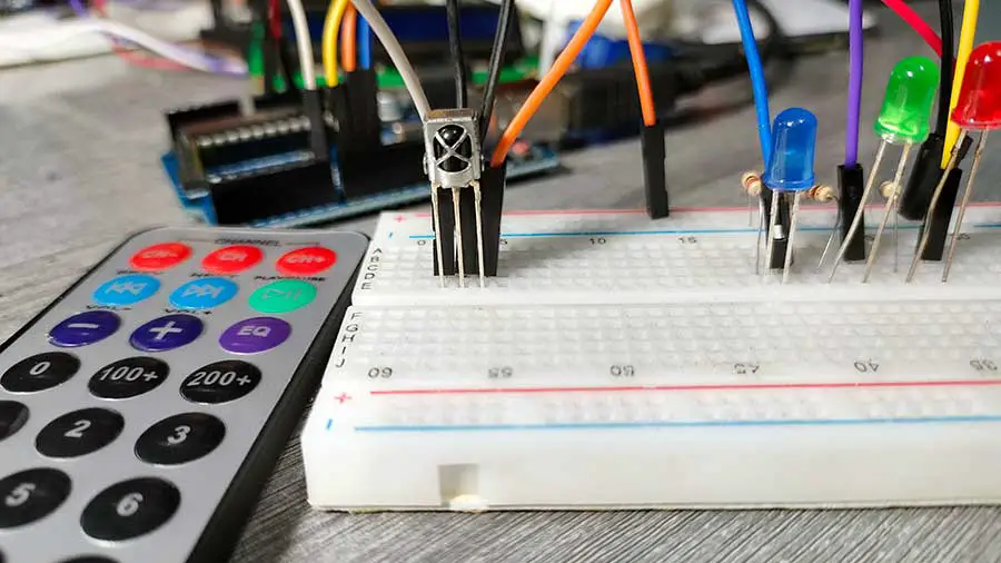
Are you looking to control devices wirelessly using an infrared remote control and an Arduino? In this guide, we'll explore how to use an IR remote control with the VS1838B IR receiver to perform basic functions with your Arduino projects. Whether you're a beginner or an enthusiast looking to expand your knowledge, this article will provide you with valuable insights and step-by-step instructions.
Imagine being able to control various electronic devices in your home with a single remote control. This can include anything from turning on lights, adjusting the volume of your stereo, or even controlling a robot. With the Arduino microcontroller and the VS1838B IR receiver, you can achieve this easily and efficiently. In this article, we'll walk you through two exciting projects:
- Checking the Value of the Remote Control Button
- Turning on Three LEDs Using the Remote Control
By the end of this guide, you'll have a solid understanding of how to decode IR signals and implement them in practical applications using Arduino.
What You'll Need
Before we dive into the projects, let's gather the necessary components:
- Arduino Uno or any compatible board
- VS1838B IR receiver module
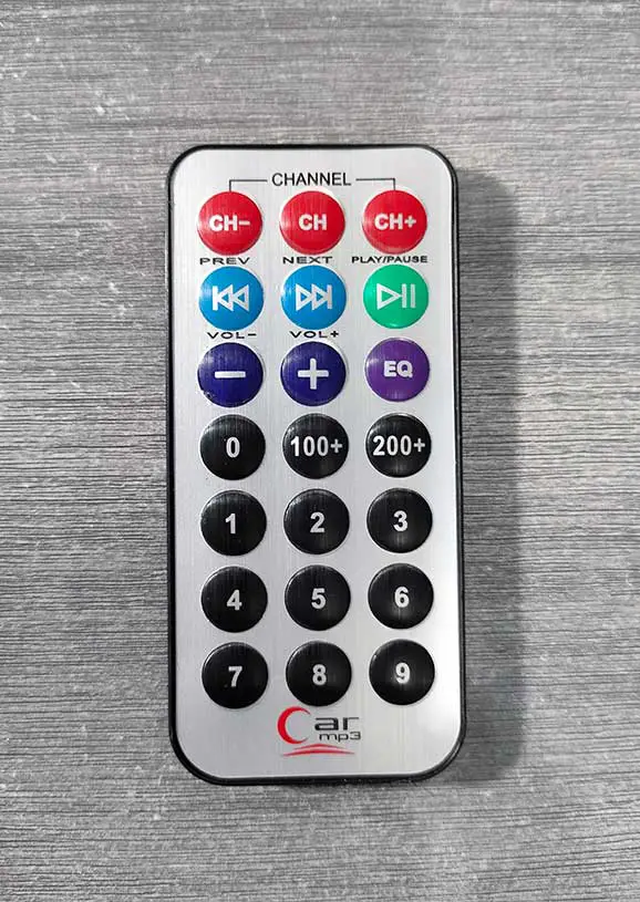
- IR remote control
- Breadboard and jumper wires
- 3 LEDs (preferably red, green, and blue)
- 3 resistors (220 ohms each)
Understanding the VS1838B IR Receiver
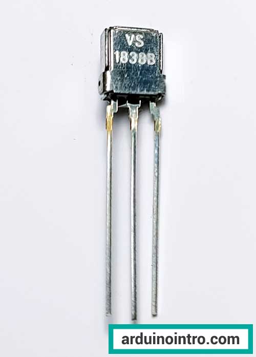
The VS1838B IR receiver is a crucial component in this project, enabling the Arduino to receive and decode signals from an infrared remote control. This section provides an overview of the VS1838B IR receiver, its features, and how it works within your Arduino projects.
What is the VS1838B IR Receiver?
The VS1838B is a high-performance infrared receiver module designed for IR remote control systems. It is widely used in various electronic devices to decode signals from remote controls, allowing for wireless control of gadgets, appliances, and DIY projects.
Key Features of the VS1838B IR Receiver
- High Sensitivity: The VS1838B has high sensitivity to infrared signals, ensuring reliable reception from a distance.
- Low Power Consumption: This receiver operates with minimal power consumption, making it suitable for battery-operated projects.
- Wide Angle Reception: It offers a wide reception angle, allowing for greater flexibility in remote control usage.
- Integrated Filter: The VS1838B includes a built-in filter to minimize interference from ambient light and other sources.
How the VS1838B IR Receiver Works
When an IR remote button is pressed, it emits an infrared light signal. The VS1838B receives this signal and converts it into a readable format for the Arduino. The IR receiver filters out any ambient light interference and decodes the signal into a binary code. This binary code corresponds to the specific button pressed on the remote.
The IRremote library in Arduino helps in decoding this binary signal into a hexadecimal format, which can be used to identify the remote control buttons. By associating these hex codes with specific actions in your Arduino code, you can control various components, such as LEDs, motors, or other electronic devices.
You can download this library at the end of this article.
Project 1: Checking the Value of the Remote Control Button
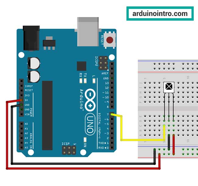
Step 1: Setting Up the Hardware
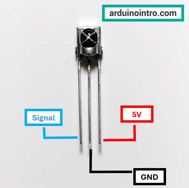
- Connect the VS1838B IR receiver to your Arduino:
- GND pin of the IR receiver to GND on the Arduino
- VCC pin of the IR receiver to 5V on the Arduino
- OUT pin of the IR receiver to Digital Pin 7 on the Arduino
Here is the breadboard circuit for this project:
Step 2: Installing the IRremote Library
To decode the signals from your remote control, you need to install the IRremote library. Click the button below to download the library.
To install the library, follow the procedure below:
- Go to Sketch->Include Library->Add .Zip Library...
- Browse to where you downloaded the zip file of the library. Do not unzip the file.
- Select the zip file and click Open.
That's it the library is now installed.
Step 3: Writing the Code
Here's the code to check the value of the remote control button:
#include <IRremote.h>

const int RECV_PIN = 7;
IRrecv irrecv(RECV_PIN);
decode_results results;

void setup(){
  Serial.begin(9600);
  irrecv.enableIRIn();
  irrecv.blink13(true);
}

void loop(){
  if (irrecv.decode(&results)){
        Serial.println(results.value);
        irrecv.resume();
  }
  delay(100);
}
Step 4: Uploading the Code and Testing
- Connect your Arduino to your computer.
- Upload the code to your Arduino.
- Open the Serial Monitor (Ctrl+Shift+M) in the Arduino IDE (set the baud rate to 9600).
- Point your IR remote at the receiver and press any button.
You should see the numeric value of each button press displayed in the Serial Monitor. This value is unique to each button and can be used to control different functions in your projects.
Here is the video of my output for this project:
Explanation of the Arduino Code
Let's break down the code step-by-step to understand what each part does.
1. Including the IRremote Library
#include <IRremote.h>
This line includes the IRremote library, which contains all the necessary functions and definitions to work with infrared (IR) communication using Arduino. This library allows the Arduino to receive and decode IR signals from an IR remote.
2. Declaring Constants and Objects
const int RECV_PIN = 7;
IRrecv irrecv(RECV_PIN);
decode_results results;
const int RECV_PIN = 7;declares a constant integerRECV_PINand assigns it the value7. This constant represents the pin number on the Arduino where the output pin of the IR receiver is connected.IRrecv irrecv(RECV_PIN);creates anIRrecvobject namedirrecv. This object will handle the reception of IR signals, and it's initialized with theRECV_PIN(pin 7 in this case).decode_results results;declares adecode_resultsobject namedresults. This object will store the data of the decoded IR signal.
3. Setting Up the Arduino
void setup(){
  Serial.begin(9600);
  irrecv.enableIRIn();
  irrecv.blink13(true);
}
void setup(){...}defines thesetupfunction, which runs once when the Arduino is powered on or reset.Serial.begin(9600);initializes serial communication at a baud rate of 9600 bits per second. This allows the Arduino to send data to the serial monitor on your computer.irrecv.enableIRIn();starts the IR receiver. This function configures theirrecvobject to begin listening for IR signals.irrecv.blink13(true);enables blinking of the built-in LED on pin 13 whenever an IR signal is received. This is useful for visually confirming that the Arduino is receiving IR signals.
4. Main Loop
void loop(){
  if (irrecv.decode(&results)){
    Serial.println(results.value);
    irrecv.resume();
  }
  delay(100);
}
void loop(){...}defines theloopfunction, which runs repeatedly as long as the Arduino is powered on.if (irrecv.decode(&results)){...}checks if an IR signal has been received and decoded successfully. Thedecodefunction returnstrueif a signal is decoded and stores the decoded result in theresultsobject.- If a signal is decoded:
Serial.println(results.value);prints the decoded value of the IR signal to the serial monitor. Theresults.valueholds the unique code sent by the button press on the IR remote.irrecv.resume();prepares the IR receiver to receive the next signal. This is necessary to reset the receiver and continue listening for new signals.
- If a signal is decoded:
delay(100);pauses the program for 100 milliseconds. This short delay helps to debounce the input and prevents reading the same signal multiple times in quick succession.
This code sets up an Arduino to receive and decode IR signals using the IRremote library. The setup function initializes the serial communication and the IR receiver. The loop function continuously checks for received IR signals, prints the decoded value to the serial monitor, and prepares the receiver for the next signal. The built-in LED on pin 13 blinks when a signal is received, providing a visual indicator. This setup allows you to capture and observe the unique codes sent by different buttons on an IR remote.
Project 2: Turning on Three LEDs Using the Remote Control
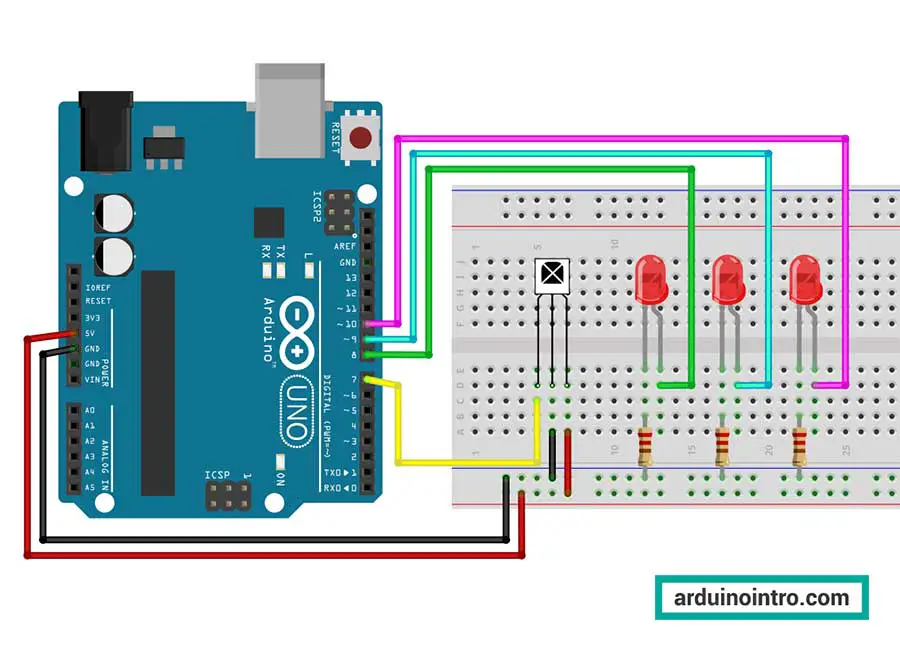
Step 1: Setting Up the Hardware
- Connect three LEDs to your breadboard.
- Connect the cathode (short leg) of each LED to a separate resistor, then connect each resistor to the GND rail on the breadboard.
- Connect the anode (long leg) of each LED to the following Arduino digital pins:
- Red LED to Digital Pin 8
- Green LED to Digital Pin 9
- Blue LED to Digital Pin 10
Here is the breadboard circuit:
Step 2: Writing the Code
We'll use the button values from the first project to control the LEDs. Update the code as follows:
#include <IRremote.h>

int IR_Recv = 7;
int bluePin = 10;
int greenPin = 9;
int redPin = 8;

IRrecv irrecv(IR_Recv);
decode_results results;

void setup(){
  Serial.begin(9600);  //starts serial communication
  irrecv.enableIRIn(); // Starts the receiver
  pinMode(bluePin, OUTPUT);
  pinMode(greenPin, OUTPUT);
  pinMode(redPin, OUTPUT);

}

void loop(){
  //decodes the infrared input
  if (irrecv.decode(&results)){
    long int decCode = results.value;
    Serial.println(results.value);
    //switch case to use the selected remote control button
    switch (results.value){
      case 16724175: // 1 button
        digitalWrite(bluePin, HIGH);
        break;

      case 16718055: // 2 button
        digitalWrite(bluePin, LOW);
        break;

       case 16743045: // 3 button
        digitalWrite(greenPin, HIGH);
        break;

       case 16716015: // 4 button
        digitalWrite(greenPin, LOW);
        break;

       case 16726215: // 5 button
        digitalWrite(redPin, HIGH);
        break;

       case 16734885: // 6 button
        digitalWrite(redPin, LOW);
        break;

       case 16738455: // 0 button
        digitalWrite(bluePin, LOW);
        digitalWrite(greenPin, LOW);
        digitalWrite(redPin, LOW);
        break;

       case 16732845: // 9 button
        digitalWrite(bluePin, HIGH);
        digitalWrite(greenPin, HIGH);
        digitalWrite(redPin, HIGH);
        break;
    }
    irrecv.resume(); // Receives the next value from the button you press
  }
  delay(100);
}
Step 3: Uploading the Code and Testing
- Upload the code to your Arduino.
- Open the Serial Monitor in the Arduino IDE.
- Press the buttons on your remote that correspond to the
RED_BUTTON,GREEN_BUTTON, andBLUE_BUTTONvalues.
You should see the respective LEDs light up when you press the designated buttons.
Here is the video of my output for this project:
Explanation of the Code:
1. Including the IRremote Library
#include <IRremote.h>
This line includes the IRremote library, which provides functions and definitions necessary for working with infrared (IR) communication using Arduino. This library allows the Arduino to receive and decode IR signals from an IR remote control.
2. Declaring Constants and Objects
int IR_Recv = 7;
int bluePin = 10;
int greenPin = 9;
int redPin = 8;

IRrecv irrecv(IR_Recv);
decode_results results;
int IR_Recv = 7;assigns the pin number 7 to the variableIR_Recv, where the IR receiver's output pin is connected.int bluePin = 10;,int greenPin = 9;, andint redPin = 8;assign the pin numbers 10, 9, and 8 to the variablesbluePin,greenPin, andredPinrespectively, where the blue, green, and red LEDs are connected.IRrecv irrecv(IR_Recv);creates anIRrecvobject namedirrecv, which is initialized with theIR_Recvpin.decode_results results;declares adecode_resultsobject namedresultsto store the decoded IR signal data.
3. Setting Up the Arduino
void setup(){
  Serial.begin(9600);  // Starts serial communication at 9600 baud rate
  irrecv.enableIRIn(); // Starts the IR receiver
  pinMode(bluePin, OUTPUT); // Sets the blue LED pin as an output
  pinMode(greenPin, OUTPUT); // Sets the green LED pin as an output
  pinMode(redPin, OUTPUT); // Sets the red LED pin as an output
}
void setup(){...}defines thesetupfunction, which runs once when the Arduino is powered on or reset.Serial.begin(9600);initializes serial communication at a baud rate of 9600 bits per second.irrecv.enableIRIn();starts the IR receiver to begin listening for IR signals.pinMode(bluePin, OUTPUT);,pinMode(greenPin, OUTPUT);, andpinMode(redPin, OUTPUT);configure the blue, green, and red LED pins as output pins.
4. Main Loop
void loop(){
  // Decodes the infrared input
  if (irrecv.decode(&results)){
    long int decCode = results.value;
    Serial.println(results.value);
    // Switch case to use the selected remote control button
    switch (results.value){
      case 16724175: // When you press the 1 button
        digitalWrite(bluePin, HIGH);
        break;
      case 16718055: // When you press the 2 button
        digitalWrite(bluePin, LOW);
        break;
      case 16743045: // When you press the 3 button
        digitalWrite(greenPin, HIGH);
        break;
      case 16716015: // When you press the 4 button
        digitalWrite(greenPin, LOW);
        break;
      case 16726215: // When you press the 5 button
        digitalWrite(redPin, HIGH);
        break;
      case 16734885: // When you press the 6 button
        digitalWrite(redPin, LOW);
        break;
      case 16738455: // When you press the 0 button
        digitalWrite(bluePin, LOW);
        digitalWrite(greenPin, LOW);
        digitalWrite(redPin, LOW);
        break;
      case 16732845: // When you press the 9 button
        digitalWrite(bluePin, HIGH);
        digitalWrite(greenPin, HIGH);
        digitalWrite(redPin, HIGH);
        break;
    }
    irrecv.resume(); // Receives the next value from the button you press
  }
  delay(100);
}
void loop(){...}defines theloopfunction, which runs repeatedly as long as the Arduino is powered on.if (irrecv.decode(&results)){...}checks if an IR signal has been received and decoded successfully.long int decCode = results.value;stores the decoded IR signal value in the variabledecCode.Serial.println(results.value);prints the decoded value to the serial monitor for debugging and verification.switch (results.value){...}uses a switch-case structure to execute different actions based on the decoded IR signal value:case 16724175:turns on the blue LED when the 1 button on the remote is pressed.case 16718055:turns off the blue LED when the 2 button on the remote is pressed.case 16743045:turns on the green LED when the 3 button on the remote is pressed.case 16716015:turns off the green LED when the 4 button on the remote is pressed.case 16726215:turns on the red LED when the 5 button on the remote is pressed.case 16734885:turns off the red LED when the 6 button on the remote is pressed.case 16738455:turns off all LEDs when the 0 button on the remote is pressed.case 16732845:turns on all LEDs when the 9 button on the remote is pressed.
irrecv.resume();resets the IR receiver to prepare for the next signal.
delay(100);pauses the program for 100 milliseconds to prevent reading the same signal multiple times in quick succession.
Don't forget to change the button values according to your IR remote control.
Practical Application
These projects demonstrate how you can use an IR remote control to interact with your Arduino. You can expand on these concepts to create more complex systems such as home automation, remote-controlled vehicles, or even a universal remote for all your DIY projects.
Frequently Asked Questions (FAQ)
Q1: Can I use a different pin for the IR receiver on the Arduino?
A1: Yes, you can use any digital pin on the Arduino for the IR receiver. Just make sure to update the pin number in the code accordingly (e.g., int IR_Recv = 7; should match the pin you use).
Q2: What should I do if my IR remote control is not working with the Arduino?
A2: If your IR remote control is not working, check the following:
- Ensure the connections are correct and secure.
- Verify that the IR remote has working batteries.
- Make sure the IR receiver is properly connected to the Arduino.
- Check the serial monitor for received values to see if the Arduino is decoding any signals.
- Ensure you have the correct values for your remote control buttons.
Q3: Can I control more than three LEDs with this setup?
A3: Yes, you can control more LEDs by assigning additional pins on the Arduino for the LEDs and updating the code to include new cases for the additional remote control buttons. Ensure you have enough available pins on the Arduino for your desired number of LEDs.
Q4: How can I open the Serial Monitor?
A4: You can open the Serial Monitor by going to Tools->Serial Monitor, or pressing the shortcut key: Ctrl+Shift+M.
Conclusion
Working with an IR remote control and the VS1838B IR receiver opens up a world of possibilities for controlling your Arduino projects wirelessly. This guide provided you with the fundamental skills needed to read IR signals and use them to control LEDs. By following these steps, you can experiment with various applications and bring your projects to life.


