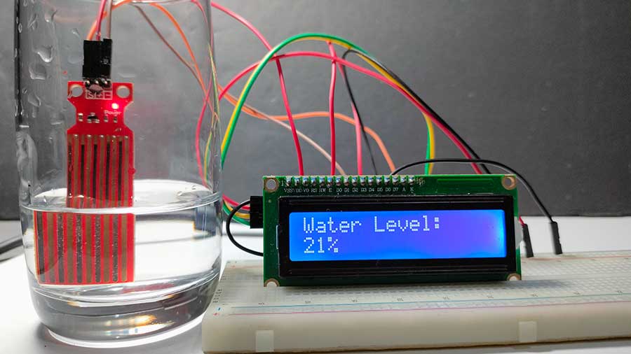
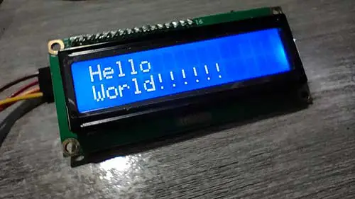
Have you ever thought about building a water level monitoring system but didn’t know where to start? Whether you’re new to Arduino or just looking for an easy and practical project, you’re in the right place. In this guide, we’ll show you how to use a water level sensor with an I2C LCD to create a simple monitoring system powered by Arduino.
For a more detailed explanation of the water level sensor, check out this article: How to Use a Water Level Sensor with Arduino: A Step-by-Step Guide
Why Monitor Water Levels?
Water level monitoring is essential for various applications:
- Smart Water Tanks: Prevent overflows or running dry.
- Hydroponics: Keep water at optimal levels for plant health.
- Rainwater Harvesting: Track collected water in storage tanks.
- Flood Detection: Get early warnings in flood-prone areas.
By using Arduino, you can create a system that’s both affordable and customizable for your needs.
What You’ll Need
To build your water level monitoring system, you’ll need these components:
- Arduino Board (e.g., Uno, Nano, or any compatible board)
- Water Level Sensor
- I2C LCD Module (16x2 LCD with I2C interface)
- Jumper Wires
- Breadboard
- USB Cable
Learn more about I2C LCD
|
|
For detailed knowledge about I2C LCD, read this article: Displaying Characters Using the I2C Liquid Crystal Display (LCD) (This link opens in another window) |
How to Wire Everything Up
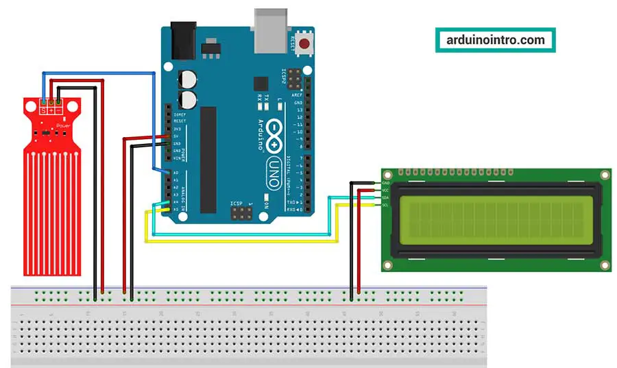
Here’s a quick breakdown of the connections:
1. Water Level Sensor
- VCC: Connect to Arduino’s 5V pin.
- GND: Connect to Arduino’s GND pin.
- Signal Pin (S): Connect to Arduino’s analog pin A0.
2. I2C LCD Module
- SDA: Connect to Arduino’s SDA pin (A4 on the Uno).
- SCL: Connect to Arduino’s SCL pin (A5 on the Uno).
- VCC: Connect to Arduino’s 5V pin.
- GND: Connect to Arduino’s GND pin.
Make sure the connections are secure to avoid glitches in the sensor readings or the LCD display.
Arduino Code
This code reads data from a water level sensor and displays the water level percentage on an I2C LCD. Here’s the code to get your water level sensor and I2C LCD up and running:
#include <Wire.h>
#include <LiquidCrystal_I2C.h>

// Set up the I2C LCD address (usually 0x27)
LiquidCrystal_I2C lcd(0x27, 2, 1, 0, 4, 5, 6, 7, 3, POSITIVE);

// Define the water level sensor pin
int waterLevelPin = A0;

void setup() {
  lcd.begin(16,2);           // Initialize the LCD
  lcd.backlight();       // Turn on the backlight
  lcd.print("Water Level:"); // Display a welcome message
  delay(2000);           // Wait for 2 seconds before starting
}

void loop() {
  int waterLevel = analogRead(waterLevelPin);       // Read data from the sensor
  int levelPercentage = map(waterLevel, 0, 1023, 0, 100); // Convert to percentage

  lcd.setCursor(0, 0);   // Set cursor to the first row
  lcd.print("Water Level:");
  lcd.setCursor(0, 1);   // Set cursor to the second row
  lcd.print(levelPercentage);
  lcd.print("%   ");     // Display percentage with extra spaces to clear old values

  delay(1000);           // Update every second
}
Code Breakdown
1. Including Libraries
#include <Wire.h>
#include <LiquidCrystal_I2C.h>
Wire.h: Enables communication between Arduino and I2C devices, such as the LCD.LiquidCrystal_I2C.h: Provides functions for interfacing with I2C LCD modules.
These libraries allow you to control the I2C LCD and simplify the process of displaying text on it.
You can download both libraries here: Displaying Characters Using the I2C Liquid Crystal Display (LCD)
2. Initializing the LCD
LiquidCrystal_I2C lcd(0x27, 2, 1, 0, 4, 5, 6, 7, 3, POSITIVE);
- The
0x27is the I2C address of the LCD. This might vary depending on your module, so you can use an I2C scanner if needed. - The other parameters (
2, 1, 0, ...) define the pin mapping between the Arduino and the LCD. These details are specific to your LCD's internal configuration.
The POSITIVE flag specifies that the backlight control pin is active high, meaning sending a HIGH signal will turn the backlight on.
3. Defining the Water Level Sensor Pin
int waterLevelPin = A0;
The water level sensor is connected to analog pin A0. This pin reads the sensor's analog voltage, which represents the water level.
4. Setup Function
void setup() {
  lcd.begin(16,2);           // Initialize the LCD for 16 columns and 2 rows
  lcd.backlight();           // Turn on the LCD backlight
  lcd.print("Water Level:"); // Display a welcome message
  delay(2000);               // Wait for 2 seconds
}
lcd.begin(16,2): Configures the LCD to have 16 columns and 2 rows.lcd.backlight(): Ensures the backlight is turned on for better visibility.lcd.print("Water Level:"): Displays the static text "Water Level:" on the LCD.delay(2000): Introduces a 2-second delay to let the user read the welcome message.
5. Loop Function
The loop() function continuously reads data from the sensor, processes it, and displays the water level percentage.
a. Reading the Sensor
int waterLevel = analogRead(waterLevelPin);
analogRead(waterLevelPin): Reads the analog voltage from the sensor pin A0. The value ranges from 0 (0V) to 1023 (5V).
b. Converting the Sensor Reading
int levelPercentage = map(waterLevel, 0, 1023, 0, 100);
map(waterLevel, 0, 1023, 0, 100): Converts the sensor value (0–1023) to a percentage (0–100). This percentage represents the water level.
c. Displaying Data on the LCD
lcd.setCursor(0, 0);
lcd.print("Water Level:");
lcd.setCursor(0, 1);
lcd.print(levelPercentage);
lcd.print("%   ");
lcd.setCursor(0, 0): Moves the cursor to the first row and first column.lcd.print("Water Level:"): Displays the text "Water Level:" on the first row.lcd.setCursor(0, 1): Moves the cursor to the second row and first column.lcd.print(levelPercentage): Displays the water level percentage on the second row.lcd.print("% "): Appends a percentage symbol and extra spaces to clear any leftover characters from previous readings.
d. Delay
delay(1000);
Introduces a 1-second pause between updates to make the display easier to read and avoid rapid fluctuations.
Practical Applications
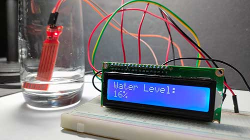
- Water Tank Monitoring: Use the percentage to keep track of your tank’s water level.
- Flood Alerts: Set thresholds to trigger warnings when the water level rises dangerously high.
- Hydroponics Systems: Maintain optimal water levels for plants.
Troubleshooting Tips
-
I2C LCD Not Displaying Data:
Check the I2C address of your LCD. Refer to your LCD's technical specifications. -
Sensor Giving Unstable Readings:
Ensure the sensor is securely wired and clean. Unstable voltage readings may indicate a faulty sensor or interference. Change jumper wires if necessary. -
Code Compilation Errors:
Make sure the required libraries (Wire.handLiquidCrystal_I2C.h) are installed in your Arduino IDE.
FAQs
1. What is an I2C LCD, and why use it?
An I2C LCD reduces the number of pins required to connect to Arduino. Instead of using 8-10 pins for a standard LCD, I2C only needs two pins (SDA and SCL), leaving more pins free for other components.
2. Can I use a different Arduino board?
Yes! This project works with any Arduino board, such as the Mega, Nano, or Leonardo, as long as it supports analog pins for the sensor and I2C communication for the LCD.
Final Thoughts
By completing this project, you’ve learned how to interface a water level sensor with an I2C LCD and Arduino to build a basic water level monitoring system. This knowledge is a stepping stone to more advanced IoT projects like integrating this setup with a Wi-Fi module for remote monitoring.
If you found this guide helpful, feel free to share it with fellow Arduino enthusiasts. Have questions or ideas for improving this project? Let us know in the comments below!

