Ever wanted to enhance your DIY projects with a bit of tech magic? Imagine creating your own access control system, just like the ones you see in offices and secured buildings. With an Arduino, an RC522 RFID module, and an I2C LCD display, you can easily build a system that uses RFID cards to grant or deny access. This beginner-friendly project not only helps you dive into the world of Arduino but also gives you a practical and rewarding application.
By the end of this tutorial, you'll have a working system where RFID cards grant or deny access, displaying messages on an LCD screen. Ready to dive into the world of RFID and Arduino? Let's get started!
What is an RFID Access Control System?
An RFID (Radio Frequency Identification) access control system allows you to use RFID cards to grant or deny access to a restricted area. This type of system is commonly used in office buildings, hotels, and secure facilities. The RC522 RFID module is a popular choice for such projects due to its ease of use and compatibility with the Arduino platform. Paired with an I2C LCD display, this system can provide real-time feedback to the user.
You can read more about the RC522 RFID module in this article: How to Use RFID RC522 with Arduino: A Complete Beginner's Guide
Materials Needed
To build this project, you will need the following components:
- Arduino Uno
- RC522 RFID module
- I2C LCD display (16x2)
- Breadboard
- Jumper wires
- RFID cards or tags
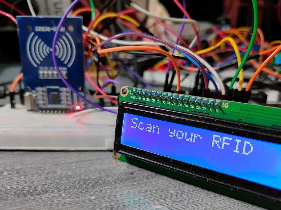
This is my output:
Step-by-Step Guide to Building the Access Control System
Step 1: Connecting the RC522 RFID Module
First, let's connect the RC522 RFID module to the Arduino. The RC522 module communicates via SPI (Serial Peripheral Interface). Here are the connections you need to make:
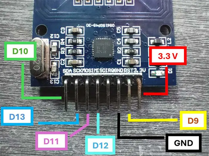
- 3.3V: Connect to 3.3V on the Arduino
- GND: Connect to GND on the Arduino
- SDA: Connect to pin 10 on the Arduino
- SCK: Connect to pin 13 on the Arduino
- MOSI: Connect to pin 11 on the Arduino
- MISO: Connect to pin 12 on the Arduino
- RST: Connect to pin 9 on the Arduino
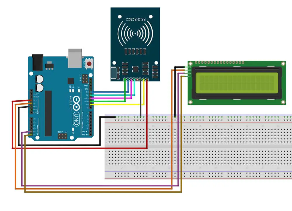
Step 2: Connecting the I2C LCD Display
Next, connect the I2C LCD display to the Arduino. The I2C LCD uses the I2C protocol, which requires only two connections:
- SDA: Connect to A4 on the Arduino
- SCL: Connect to A5 on the Arduino
Additionally, connect the power pins:
- VCC: Connect to 5V on the Arduino
- GND: Connect to GND on the Arduino
You can read more about the I2C LCD in this article: Displaying Characters Using the I2C Liquid Crystal Display (LCD)
Here is the complete breadboard circuit that I made:
Step 3: Installing the Required Libraries
Before we proceed with the code, you need to install the necessary libraries. Open the Arduino IDE and go to Sketch > Include Library > Manage Libraries. Search for and install the following libraries:
- MFRC522 by GithubCommunity
- LiquidCrystal_I2C
- Wire
You may also download these libraries at the end of this article.
Step 4: Writing the Arduino Code
Here is the Arduino code for our access control system:
#include <Wire.h>
#include <LiquidCrystal_I2C.h>
#include <MFRC522.h>
#include <SPI.h>

// Define the pins for the RC522 module
#define SS_PIN 10
#define RST_PIN 9

// Create instances of the MFRC522 and LiquidCrystal_I2C classes
MFRC522 rfid(SS_PIN, RST_PIN);
LiquidCrystal_I2C lcd(0x27, 2, 1, 0, 4, 5, 6, 7, 3, POSITIVE);

// Known RFID card UID (Change this to match your card's UID)
byte knownUID[4] = {0x7B, 0xC0, 0xAD, 0x21};

void setup() {
  // Initialize serial communication
  Serial.begin(9600);
  // Initialize SPI bus
  SPI.begin();
  // Initialize RFID module
  rfid.PCD_Init();

  // Initialize I2C LCD
  lcd.begin(16,2);
  lcd.backlight();

  // Display a welcome message
  lcd.setCursor(0, 0);
  lcd.print("Access Control");
  lcd.setCursor(0, 1);
  lcd.print("System Ready");
  delay(2000);
  lcd.clear();
  lcd.print("Scan your RFID");
}

void loop() {
  //lcd.print("Scan your RFID");
  // Look for new RFID cards
  if (rfid.PICC_IsNewCardPresent() && rfid.PICC_ReadCardSerial()) {
    // Print the UID of the card
    Serial.print("UID tag: ");
    for (byte i = 0; i < rfid.uid.size; i++) {
      Serial.print(rfid.uid.uidByte[i] < 0x10 ? " 0" : " ");
      Serial.print(rfid.uid.uidByte[i], HEX);
    }
    Serial.println();

    // Check if the card UID matches the known UID
    if (checkUID(rfid.uid.uidByte)) {
      lcd.clear();
      lcd.setCursor(0, 0);
      lcd.print("Access Granted");
      lcd.setCursor(0, 1);
      lcd.print("Welcome!");
    } else {
      lcd.clear();
      lcd.setCursor(0, 0);
      lcd.print("Access Denied");
      lcd.setCursor(0, 1);
      lcd.print("Invalid Card");
    }
    delay(3000);
    lcd.clear();
    lcd.print("Scan your RFID");

    // Halt PICC
    rfid.PICC_HaltA();
  }
}

// Function to check if the scanned UID matches the known UID
bool checkUID(byte* uid) {
  for (byte i = 0; i < 4; i++) {
    if (uid[i] != knownUID[i]) {
      return false;
    }
  }
  return true;
}
Step 5: Uploading the Code
Upload the code to your Arduino Uno. Once uploaded, open the Serial Monitor (set the baud rate to 9600) to see the RFID card's UID when you scan a card.
Step 6: Testing Your Access Control System
Power up your Arduino, and scan an RFID card. If the card's UID matches the known UID, the LCD will display "Access Granted" and "Welcome!". If the card is not recognized, it will display "Access Denied" and "Invalid Card".
Code Explanation
Let's break down the Arduino code step-by-step:
Including Necessary Libraries
#include <Wire.h>
#include <LiquidCrystal_I2C.h>
#include <MFRC522.h>
#include <SPI.h>
- Wire.h: This library is used for I2C communication.
- LiquidCrystal_I2C.h: This library is for controlling the I2C LCD display.
- MFRC522.h: This library allows communication with the RC522 RFID module.
- SPI.h: This library allows communication with devices using the SPI protocol.
Defining Pins
#define SS_PIN 10
#define RST_PIN 9
- SS_PIN: This is the Slave Select pin for the SPI communication with the RC522.
- RST_PIN: This is the Reset pin for the RC522.
Creating Instances
MFRC522 rfid(SS_PIN, RST_PIN);
LiquidCrystal_I2C lcd(0x27, 2, 1, 0, 4, 5, 6, 7, 3, POSITIVE);
- rfid: Creates an instance of the MFRC522 class with the specified SS and RST pins.
- lcd: Creates an instance of the LiquidCrystal_I2C class for an LCD display. The parameters define the I2C address (0x27) and the pin mapping for the LCD.
Defining a Known UID
byte knownUID[4] = {0x7B, 0xC0, 0xAD, 0x21};
knownUID: This array stores the UID of an RFID card that is considered valid.
In an RFID access control system, each RFID card has a unique identifier (UID) that can be used to distinguish one card from another. In this particular Arduino project, the UID of the card is checked to grant or deny access. The following line of code defines a known, valid UID that will be used to compare against the UID of scanned RFID cards:
How to Find and Change the Known UID
When you get an RFID card, you need to find its UID to use it in your program. You can use the following sketch to read the UID of any RFID card:
#include <SPI.h>
#include <MFRC522.h>

#define SS_PIN 10
#define RST_PIN 9

MFRC522 rfid(SS_PIN, RST_PIN);

void setup() {
  Serial.begin(9600);
  SPI.begin();
  rfid.PCD_Init();
  Serial.println("Scan an RFID card...");
}

void loop() {
  if (rfid.PICC_IsNewCardPresent() && rfid.PICC_ReadCardSerial()) {
    Serial.print("UID tag: ");
    for (byte i = 0; i < rfid.uid.size; i++) {
      Serial.print(rfid.uid.uidByte[i] < 0x10 ? " 0" : " ");
      Serial.print(rfid.uid.uidByte[i], HEX);
    }
    Serial.println();

    rfid.PICC_HaltA();
  }
}
Example Output
When you run the above sketch and scan an RFID card, you might see something like this in the Serial Monitor:
UID tag: DE AD BE EF
This output means that the UID of the scanned card is DE AD BE EF. You would then replace the knownUID array in your main code with this value:
byte knownUID[4] = {0xDE, 0xAD, 0xBE, 0xEF};
Another Example
Suppose you have another card with the UID A1 B2 C3 D4. You would update the knownUID array as follows:
byte knownUID[4] = {0xA1, 0xB2, 0xC3, 0xD4};
Setup Function
void setup() {
  Serial.begin(9600);         // Initialize serial communication at 9600 baud
  SPI.begin();                // Initialize the SPI bus
  rfid.PCD_Init();            // Initialize the RFID module

  lcd.begin(16,2);            // Initialize the LCD with 16 columns and 2 rows
  lcd.backlight();            // Turn on the LCD backlight

  lcd.setCursor(0, 0);        // Set cursor to the first column of the first row
  lcd.print("Access Control");// Print "Access Control" on the LCD
  lcd.setCursor(0, 1);        // Set cursor to the first column of the second row
  lcd.print("System Ready");  // Print "System Ready" on the LCD
  delay(2000);                // Wait for 2 seconds
  lcd.clear();                // Clear the LCD
  lcd.print("Scan your RFID");// Prompt to scan an RFID card
}
- Serial.begin(9600): Sets up serial communication for debugging.
- SPI.begin(): Initializes the SPI bus.
- rfid.PCD_Init(): Initializes the RC522 RFID module.
- lcd.begin(16,2): Initializes the LCD display with 16 columns and 2 rows.
- lcd.backlight(): Turns on the LCD backlight.
- lcd.setCursor(0, 0): Sets the cursor position to the first column of the first row.
- lcd.print("Access Control"): Prints the message "Access Control" on the first row.
- lcd.setCursor(0, 1): Sets the cursor position to the first column of the second row.
- lcd.print("System Ready"): Prints the message "System Ready" on the second row.
- delay(2000): Waits for 2 seconds before proceeding.
- lcd.clear(): Clears the LCD display.
- lcd.print("Scan your RFID"): Prompts the user to scan an RFID card.
Loop Function
void loop() {
  if (rfid.PICC_IsNewCardPresent() && rfid.PICC_ReadCardSerial()) {
    Serial.print("UID tag: ");
    for (byte i = 0; i < rfid.uid.size; i++) {
      Serial.print(rfid.uid.uidByte[i] < 0x10 ? " 0" : " ");
      Serial.print(rfid.uid.uidByte[i], HEX);
    }
    Serial.println();

    if (checkUID(rfid.uid.uidByte)) {
      lcd.clear();
      lcd.setCursor(0, 0);
      lcd.print("Access Granted");
      lcd.setCursor(0, 1);
      lcd.print("Welcome!");
    } else {
      lcd.clear();
      lcd.setCursor(0, 0);
      lcd.print("Access Denied");
      lcd.setCursor(0, 1);
      lcd.print("Invalid Card");
    }
    delay(3000);
    lcd.clear();
    lcd.print("Scan your RFID");

    rfid.PICC_HaltA();
  }
}
- rfid.PICC_IsNewCardPresent(): Checks if a new RFID card is present.
- rfid.PICC_ReadCardSerial(): Reads the UID of the RFID card.
- Serial.print("UID tag: "): Prints "UID tag: " to the Serial Monitor.
- for (byte i = 0; i < rfid.uid.size; i++): Loops through each byte of the UID.
- Serial.print(rfid.uid.uidByte[i] < 0x10 ? " 0" : " "): Prints a leading zero if the byte is less than 0x10.
- Serial.print(rfid.uid.uidByte[i], HEX): Prints the byte in hexadecimal format.
- Serial.println(): Prints a newline to the Serial Monitor.
Checking UID
if (checkUID(rfid.uid.uidByte)) {
  lcd.clear();
  lcd.setCursor(0, 0);
  lcd.print("Access Granted");
  lcd.setCursor(0, 1);
  lcd.print("Welcome!");
} else {
  lcd.clear();
  lcd.setCursor(0, 0);
  lcd.print("Access Denied");
  lcd.setCursor(0, 1);
  lcd.print("Invalid Card");
}
delay(3000);
lcd.clear();
lcd.print("Scan your RFID");
rfid.PICC_HaltA();
- checkUID(rfid.uid.uidByte): Calls the
checkUIDfunction to compare the scanned UID with the known UID. - lcd.clear(): Clears the LCD display.
- lcd.setCursor(0, 0): Sets the cursor to the first column of the first row on the LCD.
- lcd.print("Access Granted"): Prints "Access Granted" on the first row if the UID matches.
- lcd.setCursor(0, 1): Sets the cursor to the first column of the second row on the LCD.
- lcd.print("Welcome!"): Prints "Welcome!" on the second row if the UID matches.
- lcd.print("Access Denied"): Prints "Access Denied" on the first row if the UID does not match.
- lcd.print("Invalid Card"): Prints "Invalid Card" on the second row if the UID does not match.
- delay(3000): Pauses the program for 3 seconds to allow the message to be read.
- lcd.clear(): Clears the LCD display.
- lcd.print("Scan your RFID"): Prompts the user to scan another RFID card.
- rfid.PICC_HaltA(): Halts the reading of the current RFID card.
checkUID Function
bool checkUID(byte* uid) {
  for (byte i = 0; i < 4; i++) {
    if (uid[i] != knownUID[i]) {
      return false;
    }
  }
  return true;
}
- *checkUID(byte uid)**: Function to compare the scanned UID with the known UID.
- for (byte i = 0; i < 4; i++): Loops through each byte of the UID.
- if (uid[i] != knownUID[i]): Checks if the byte of the scanned UID does not match the known UID.
- return false: Returns false if any byte does not match.
- return true: Returns true if all bytes match.
Summary of the Code
This code sets up an access control system using an Arduino, RC522 RFID module, and an I2C LCD display. The system prompts the user to scan an RFID card, reads the card's UID, and checks if it matches a predefined UID. If the UID matches, it grants access and displays a welcome message on the LCD. If the UID does not match, it denies access and displays an error message. The checkUID function performs the comparison of the scanned UID with the known UID.
Conclusion
Building an RFID access control system with an RC522 RFID module and an I2C LCD display is a fantastic project for beginners in Arduino. Not only does it teach you about interfacing different modules, but it also provides a practical application that can be expanded and customized for various uses. We hope this guide has been helpful and encourages you to explore more Arduino projects.


error: 'positive' was not declared in this scope LiquidCrystal_I2C lcd(0x27, 2, 1, 0, 4, 5, 6, 7, 3, positive);
Compilation error: 'positive' was not declared in this scope
This could happen if the LiquidCrystal_I2C library was not installed. Make sure you download and install the library found in this article.
Another potential problem could be a conflict with another LCD library that has already been installed. Arduino might be referring to that library instead of this one. In that case, you must uninstall that library before installing the LCD library found here.
Also, 'positive' should be all CAPS.
Hope this helps.
I got positive' was not declared error !!I uninstalled the I2C library and installed the one provided in the description, the error code did not go away.
could you please advise what the issue.
Thank you
This could happen if the Wire library mentioned in this article is not installed. Try installing this library, close your Arduino IDE, and open it again. This might resolve the issue.