Are you wondering how to monitor soil moisture levels for your garden or agricultural project? Using a soil moisture sensor with Arduino can be a game-changer in maintaining the perfect moisture levels for your plants. This article will guide you through the process of setting up and using a soil moisture sensor with Arduino, providing a detailed explanation of the Arduino code and practical applications.
Introduction: Why Use a Soil Moisture Sensor with Arduino?
Maintaining the right soil moisture is crucial for the health of your plants. Overwatering or underwatering can cause significant damage to plant health. A soil moisture sensor connected to an Arduino can automate the monitoring process, ensuring that your plants receive just the right amount of water. This technology is particularly beneficial for:
- Home gardens
- Greenhouses
- Agricultural fields
- Indoor plant setups
With this guide, you will learn how to set up and use a soil moisture sensor with Arduino, including a step-by-step explanation of the code needed to get started.
What is a Soil Moisture Sensor?
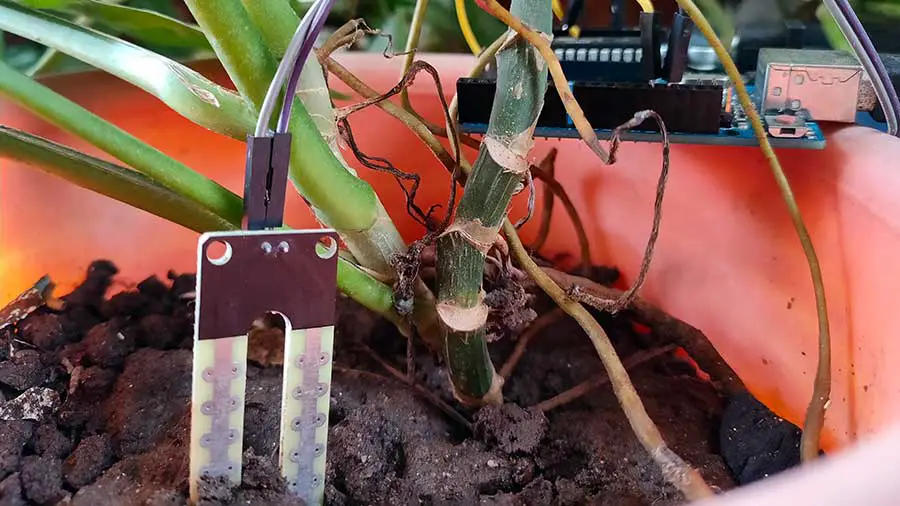
A soil moisture sensor measures the volumetric water content in the soil. It typically consists of two probes that are inserted into the soil. The sensor works by measuring the electrical resistance between the probes, which varies with the moisture content of the soil. The LM393 is an important component often found in soil moisture sensor modules. It is a dual comparator IC (Integrated Circuit) used to provide a digital output signal based on the analog input from the soil moisture sensor.
Understanding the Soil Moisture Sensor
A typical soil moisture sensor consists of two main parts: the soil moisture probe and the soil moisture module.
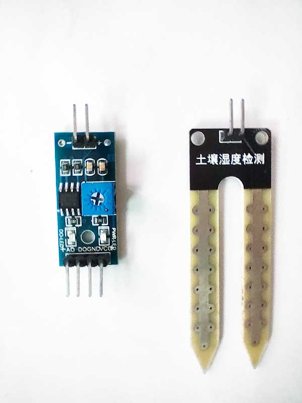
Soil Moisture Probe
The soil moisture probe is the part of the sensor that is inserted into the soil. It usually consists of two conductive metal rods (probes) that measure the resistance of the soil. The key aspects of the soil moisture probe are:
- Probes: These are the metal rods that are inserted into the soil. They measure the soil's electrical resistance, which varies with moisture content. Wet soil conducts electricity better than dry soil, leading to lower resistance.
- Durability: The probes are designed to withstand outdoor conditions, but they can corrode over time. Some probes are coated to reduce corrosion.
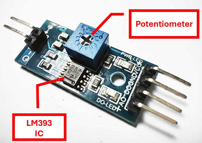
Soil Moisture Module
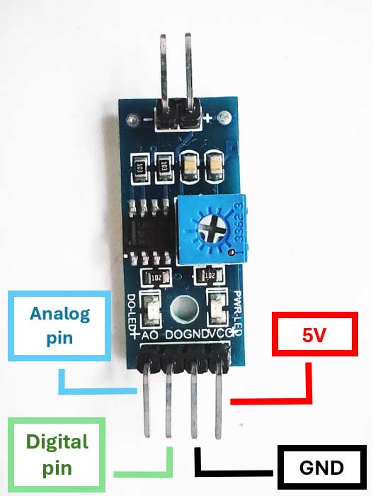
The soil moisture module processes the signals from the probe and converts them into a readable value for the Arduino. The key components of the module are:
- VCC Pin: This pin connects to the 5V power supply from the Arduino.
- GND Pin: This pin connects to the ground (GND) on the Arduino.
- Analog Output Pin (A0): This pin outputs an analog signal proportional to the soil moisture level. It connects to one of the Arduino's analog input pins.
- Digital Output Pin (D0): This pin can be used to output a digital signal. It typically has a threshold setting, where it outputs HIGH or LOW based on a predefined moisture level.
- Potentiometer: Some modules include a potentiometer to adjust the threshold for the digital output.
Components Needed
To get started, you will need the following components:
- Arduino board (e.g., Arduino Uno)
- Soil moisture sensor module
- Connecting wires
- Breadboard (optional)
- LED (optional, for visual indication)
- 220-ohm resistor (optional, for LED setup)
Step-by-Step Guide to Using a Soil Moisture Sensor with Arduino
1. Setting Up the Hardware
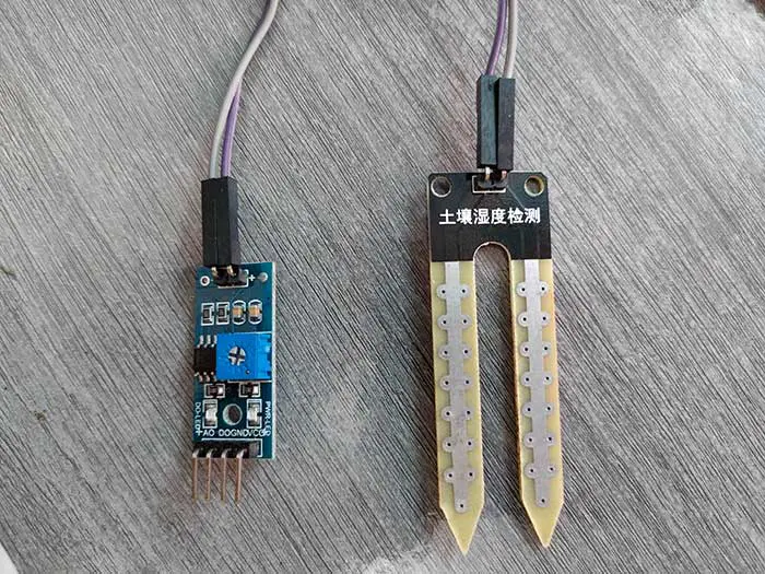
Connecting the Probe to the Module
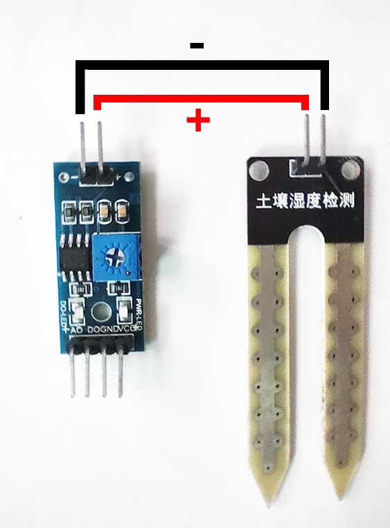
- You will need two connecting wires to link the probe to the module.
- The soil moisture probe typically has two pins or connectors.
- The soil moisture module will have corresponding connectors to attach the probe.
- Take two connecting wires and attach them to the pins on the soil moisture probe. If the probe has a dedicated connector, plug the wires into it.
- While doing this project, I noticed that the soil moisture probe can be connected either way, meaning that the positive and negative pins can be interchanged. I tried changing the connections and it still worked!
Connecting the Soil Moisture Sensor to Arduino
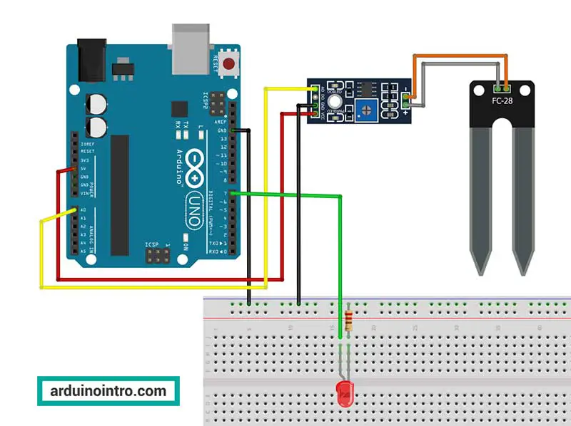
- Connect the VCC pin of the soil moisture sensor to the 5V pin on the Arduino.
- Connect the GND pin of the soil moisture sensor to the GND pin on the Arduino.
- Connect the Analog output pin (A0) of the soil moisture sensor to the A0 analog input pin on the Arduino. You may choose between the Analog output pin and the Digital output pin.
Optional: Connecting an LED for Visual Indication
- Connect the longer leg (anode) of the LED to digital pin 7 on the Arduino through a 220Ω resistor.
- Connect the shorter leg (cathode) of the LED to the GND pin on the Arduino.
2. Writing the Arduino Code
Below is the Arduino code to read the soil moisture sensor and light up an LED if the soil is too dry.
// Define the pins
int sensorPin = A0;
int ledPin = 7;

// Variables to store sensor value
int sensorValue = 0;

void setup() {
  // Initialize serial communication at 9600 baud rate
  Serial.begin(9600);

  // Initialize the LED pin as an output
  pinMode(ledPin, OUTPUT);
}

void loop() {
  // Read the analog value from the sensor
  sensorValue = analogRead(sensorPin);

  // Print the sensor value to the Serial Monitor
  Serial.print("Soil Moisture Value: ");
  Serial.println(sensorValue);

  // Check if the soil is dry
  if (sensorValue > 500) {
    // Turn the LED on
    digitalWrite(ledPin, HIGH);
  } else {
    // Turn the LED off
    digitalWrite(ledPin, LOW);
  }

  // Wait for a second before taking another reading
  delay(1000);
}
3. Explanation of the Arduino Code
Setup Function
The setup() function in an Arduino sketch is called once when the microcontroller is powered up or reset. Its primary purpose is to initialize variables, pin modes, and other libraries that are needed throughout the program. Let's break down the specific lines of code within the setup() function provided:
void setup() {
  Serial.begin(9600);
  pinMode(ledPin, OUTPUT);
}
-
void setup() {:- This line defines the
setup()function. In Arduino programming,setup()is a special function that runs once when the sketch starts. It is used to initialize the program's environment.
- This line defines the
-
Serial.begin(9600);:Serial.begin()is a function that sets up the serial communication between the Arduino board and the computer or other serial devices.- The argument
9600is the baud rate, which determines the speed of communication. In this case, it is set to 9600 bits per second. - Serial communication is essential for debugging and for sending and receiving data between the Arduino and other devices. It allows you to use the Serial Monitor in the Arduino IDE to view sensor readings and other output from the Arduino.
-
pinMode(ledPin, OUTPUT);:pinMode()is a function that configures the specified pin to behave either as an input or an output.ledPinis a variable (typically defined earlier in the code, e.g.,const int ledPin = 7;) that represents the pin number where the LED is connected.OUTPUTis a constant that tells the Arduino to set the pin as an output. When a pin is set as an output, it can send a HIGH or LOW signal to drive components like LEDs, motors, etc.
In summary, the setup() function initializes serial communication and configures the LED pin as an output. This setup is critical for the correct operation of the program, ensuring that you can monitor sensor values through the Serial Monitor and control the LED as intended.
Loop Function
void loop() {
  sensorValue = analogRead(sensorPin);
  Serial.print("Soil Moisture Value: ");
  Serial.println(sensorValue);

  if (sensorValue > 500) {
    digitalWrite(ledPin, HIGH);
  } else {
    digitalWrite(ledPin, LOW);
  }

  delay(1000);
}
The loop() function runs repeatedly and performs the following tasks:
- Reads the analog value from the soil moisture sensor.
- Prints the sensor value to the Serial Monitor.
- Checks if the soil moisture value is above a threshold (500 in this case) to determine if the soil is dry.
- Turns the LED on if the soil is dry and off if it is not.
- Waits for one second before taking another reading.
Watch a YouTube video of this article:
Step-by-Step Explanation
-
void loop() {:- This line defines the start of the
loop()function. Theloop()function runs repeatedly in an infinite loop, allowing the Arduino to perform tasks continuously.
- This line defines the start of the
-
sensorValue = analogRead(sensorPin);:analogRead(sensorPin)reads the analog input from the soil moisture sensor connected to the specified analog pin (sensorPin).- The sensor's value is an integer between 0 and 1023, representing the voltage level from 0 to 5V.
- The read value is stored in the variable
sensorValue.
-
Serial.print("Soil Moisture Value: ");:Serial.print()sends data to the Serial Monitor on the connected computer.- This line prints the text "Soil Moisture Value: " to the Serial Monitor, which acts as a label for the sensor value that follows.
-
Serial.println(sensorValue);:Serial.println()sends data to the Serial Monitor followed by a newline character, moving the cursor to the next line.- This line prints the current value of
sensorValue, which represents the soil moisture level. - The combination of
Serial.print()andSerial.println()provides a clear and readable output in the Serial Monitor.
-
if (sensorValue > 500) {:- This line begins an
ifstatement that checks if the soil moisture level is above a certain threshold (500 in this case). - The threshold value (500) is an arbitrary number and can be adjusted based on calibration for different soil moisture levels. When I tried this project, I discovered that the soil is dry if the value exceeds 500. Feel free to conduct your own observation.
- This line begins an
-
digitalWrite(ledPin, HIGH);:- If the
ifcondition is true (i.e., the soil moisture level is above the threshold),digitalWrite(ledPin, HIGH)sets the specified digital pin (ledPin) to HIGH. - Setting the pin to HIGH turns on the LED connected to that pin, indicating that the soil is too dry.
- If the
-
} else {:- This line starts the
elseblock, which is executed if theifcondition is false (i.e., the soil moisture level is above or equal to the threshold).
- This line starts the
-
digitalWrite(ledPin, LOW);:- If the
ifcondition is false,digitalWrite(ledPin, LOW)sets the specified digital pin (ledPin) to LOW. - Setting the pin to LOW turns off the LED, indicating that the soil moisture level is adequate.
- If the
-
delay(1000);:delay(1000)pauses the execution of the program for 1000 milliseconds (1 second).- This delay allows time between readings, reducing the frequency of sensor readings and giving a clear update interval on the Serial Monitor.
Practical Applications of Soil Moisture Sensor with Arduino
- Automated Irrigation System: You can integrate a relay module to control a water pump or solenoid valve based on the soil moisture readings, creating an automated irrigation system.
- Greenhouse Monitoring: Use multiple sensors to monitor different sections of a greenhouse, ensuring uniform moisture levels.
- Smart Gardening: Combine the soil moisture sensor with other sensors (e.g., temperature, humidity) to create a comprehensive smart garden system.
Tips for Using the Soil Moisture Sensor
- Calibration: Calibrate your soil moisture sensor for more accurate readings. This involves finding the sensor values for completely dry and fully saturated soil.
- Sensor Placement: Place the sensor at the root level of the plants for more relevant moisture readings.
- Avoid Corrosion: Many soil moisture sensors are prone to corrosion if left in the soil for extended periods. Consider using capacitive sensors, which are less susceptible to corrosion.
- Consistent Readings: Take multiple readings at different times to get a more consistent average soil moisture level.
- Power Supply: Ensure a stable power supply to avoid fluctuations in sensor readings.
- Environmental Factors: Be aware that temperature and soil composition can affect sensor readings. Adjust your calibration and code thresholds accordingly.
Conclusion
Using a soil moisture sensor with Arduino can significantly improve plant care by providing precise moisture monitoring. Whether you are a hobbyist or a professional, this guide provides the essential steps to get started. By following the hardware setup and Arduino code provided, you can create a reliable system to maintain optimal soil moisture levels for your plants.
If you have any questions or need further assistance, feel free to leave a comment below. This article aims to be a valuable resource for anyone looking to enhance their gardening or agricultural projects with Arduino and soil moisture sensors. Happy gardening!


