In the rapidly advancing world of technology, home automation has become increasingly popular. One key component in creating smart and responsive systems is the Passive Infrared (PIR) sensor. In this article, we will delve into the exciting realm of integrating PIR sensors with Arduino to create a simple yet effective motion detection system for your projects.
Understanding Passive Infrared Sensors
Passive Infrared Sensors are devices that can detect motion by measuring changes in the infrared (IR) radiation emitted by objects in their field of view. They are commonly used in security systems, lighting controls, and other applications where the detection of human presence is crucial.
Passive Infrared (PIR) sensors typically consist of several key components that work together to detect motion based on changes in infrared radiation. Here are the primary components of a typical PIR sensor:
-
Pyroelectric Sensor: This is the core component of the PIR sensor. It consists of a pyroelectric material that generates an electric charge when exposed to infrared radiation. The sensor is usually divided into two or more segments to detect motion across a wider area.
-
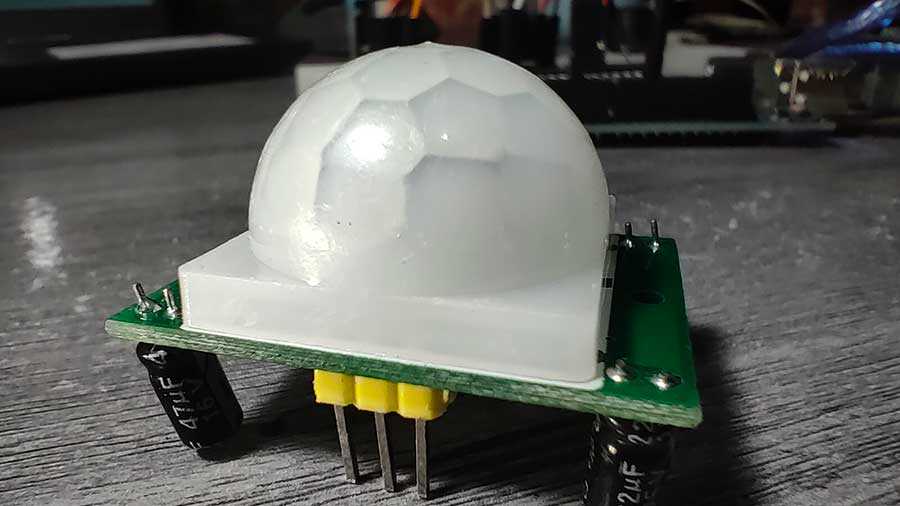
Fresnel Lens: The Fresnel lens is placed in front of the pyroelectric sensor to focus infrared radiation onto the sensor elements. It helps to improve the sensor's sensitivity and range by capturing and directing infrared energy from the surrounding environment.
How PIR Sensors Detect Motion
Passive Infrared (PIR) sensors detect motion by sensing changes in infrared radiation emitted by objects in their field of view. Here's an overview of how PIR sensors detect motion:
-
Infrared Radiation Detection: PIR sensors contain a specialized material known as a pyroelectric sensor. This material generates a voltage when exposed to infrared radiation emitted by objects in its surroundings. Infrared radiation is a form of electromagnetic radiation that is invisible to the human eye and is emitted by all objects with a temperature above absolute zero. A Fresnel lens covers the pyroelectric sensor.
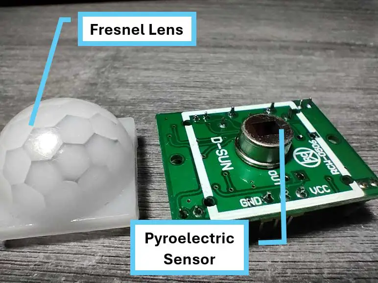
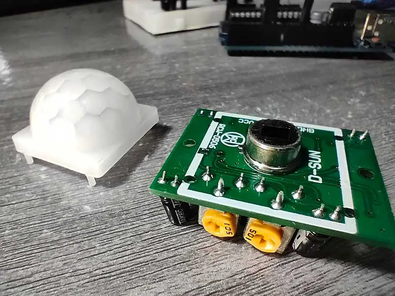
You can see the pyroelectric sensor if you remove the Fresnel lens. -
Baseline Measurement: Before detecting motion, the PIR sensor establishes a baseline voltage corresponding to the ambient infrared radiation in its surroundings. This baseline voltage represents the "normal" level of infrared radiation detected by the sensor when there is no motion.
-
Detection of Changes: When an object moves within the sensor's field of view, it emits infrared radiation that differs from the ambient radiation, causing a change in the voltage output of the pyroelectric sensor. This change is detected by the sensor's signal processing circuitry.
-
Signal Processing: The signal processing circuitry of the PIR sensor analyzes the voltage output from the pyroelectric sensor and compares it to the baseline voltage. If the voltage exceeds a certain threshold or exhibits a significant change, it indicates the presence of motion.
-
Adjustment for Sensitivity and Time Delay: PIR sensors often feature adjustments for sensitivity and time delay to customize their response to motion. Sensitivity adjustments control the threshold for detecting motion, while time delay adjustments determine how long the sensor remains active after detecting motion. This can also be programmed using Arduino.
Components Needed
- Arduino Board (e.g., Arduino Uno)
- Passive Infrared Sensor (PIR)
- Breadboard and jumper wires
- LEDs (optional for visual indication)
- Resistor (220Ω for LED)
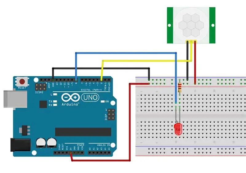
Wiring the Components
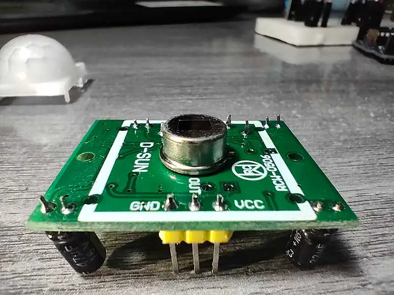
- Connect the VCC pin of the PIR sensor to the 5V pin on the Arduino.
- Connect the GND pin of the PIR sensor to the GND pin on the Arduino.
- Connect the OUT pin of the PIR sensor to a digital pin on the Arduino (e.g., pin 2).
- If using LEDs for visual indication, connect the anode of the LED to a digital pin, and the cathode through a resistor to the GND pin.
Coding the Arduino
int pirPin = 2;  // Digital pin connected to the PIR sensor
int ledPin = 8; // Digital pin connected to the LED (optional)

void setup() {
  pinMode(pirPin, INPUT);
  pinMode(ledPin, OUTPUT);
  Serial.begin(9600);
}

void loop() {
  int pirState = digitalRead(pirPin);

  if (pirState == HIGH) {
    digitalWrite(ledPin, HIGH);  // Turn on the LED (optional)
    Serial.println("Motion detected!");
    delay(1000);  // Optional delay to avoid repeated detection
  } else {
    digitalWrite(ledPin, LOW);   // Turn off the LED (optional)
  }
}
Explanation:
- The PIR sensor output is read using
digitalRead()on the specified digital pin. - If motion is detected (HIGH signal), the LED is turned on, and a message is sent to the Serial Monitor.
- Adjust the delay according to your project's requirements to prevent rapid and repeated detection.
Testing the System:
- Upload the code to your Arduino.
- Open the Serial Monitor to observe the detection messages.
- Move in front of the PIR sensor and observe the LED (if connected) lighting up.
Here's a demonstration:
Let's break down the code a little further.
int pirState = digitalRead(pirPin);This line reads the digital state (either HIGH or LOW) of the pin specified by pirPin (pin 2), where the PIR sensor is connected. The result is stored in the variable pirState, indicating whether motion is detected or not.
if (pirState == HIGH) {
This line begins an if statement, which checks whether the value of pirState is HIGH, indicating that motion is detected by the PIR sensor.
Serial.println("Motion detected!");
Here, a message "Motion detected!" is sent via serial communication, which can be monitored using the Serial Monitor in the Arduino IDE or another serial communication program.
delay(1000);
This line introduces a delay of 1000 milliseconds (1 second). It's optional and used to prevent repeated detection of motion within a short time frame, providing stability to the detection system.
Watch a YouTube video of this article:
Practical Uses of Passive Infrared Sensors
Real-life applications of using PIR sensors are diverse and offer a wide range of possibilities for home automation projects. By integrating PIR sensors into your system, you can create a smart and efficient environment that enhances security, convenience, and energy management. One practical application of PIR sensors is in security systems. With their motion detection capabilities, PIR sensors can detect any movement within their range and trigger an alarm or notification. This is particularly useful for detecting intruders or unauthorized access to your property, providing an added layer of security.
Another application is in lighting control. By integrating PIR sensors with lighting systems, you can automate the activation and deactivation of lights based on occupancy. This means that lights will only turn on when someone is present in the area, saving energy and providing convenience
Conclusion
Integrating a Passive Infrared Sensor with Arduino opens up a world of possibilities for creating responsive and intelligent systems. From security applications to energy-efficient lighting, the combination of PIR sensors and Arduino allows hobbyists and developers to explore the exciting field of home automation. Experiment with the code and expand the system to suit your specific project needs, bringing your ideas to life with the power of motion detection.


