Are you looking to monitor the water level in a tank or a reservoir? Using a water level sensor with Arduino is a practical and effective solution for many applications, from home automation systems to agricultural irrigation management.
In this comprehensive guide, we'll walk you through the process of setting up a water level sensor with an Arduino board, provide a detailed Arduino code, and explain each step of the code to help you understand how it all works. Whether you are a hobbyist or a professional, this article will be a valuable resource for you.
What is a Water Level Sensor?
A water level sensor measures the level of water in a container. It can be used in various practical applications such as:
- Home Water Tanks: Automate the refilling process when the water level drops below a certain point.
- Irrigation Systems: Ensure your plants receive the right amount of water.
- Industrial Water Management: Monitor and control the water levels in industrial reservoirs or storage tanks.
Components Needed
To get started, you will need the following components:
- Arduino Uno board
- Water level sensor
- Breadboard
- Jumper wires
- LED (optional for visual indication)
- Resistor (220 ohms if using an LED)
- USB cable to connect Arduino to your computer
Step-by-Step Guide to Setting Up Your Water Level Sensor with Arduino
1. Connect the Water Level Sensor to Arduino
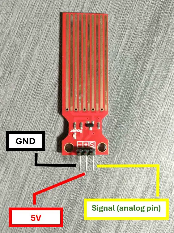
First, let's connect the water level sensor to the Arduino. Most water level sensors have three pins: VCC (+), GND (-), and SIG (signal).
- VCC (+): Connect this pin to the 5V pin on the Arduino.
- GND (-): Connect this pin to the GND pin on the Arduino.
- SIG (S): Connect this pin to an analog input pin on the Arduino (e.g., A0).
2. Connect an LED for Visual Indication (Optional)
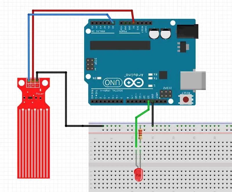
You can also connect an LED to indicate the water level visually. Connect the longer leg (anode) of the LED to a digital pin on the Arduino (e.g., D13) through a 220-ohm resistor, and the shorter leg (cathode) to the GND.
Here's the complete breadboard circuit:
3. Write the Arduino Code
Below is the Arduino code to read the water level and light up an LED when the water level rises above a certain threshold.
// Define the pins
int waterSensorPin = A0;  // Water level sensor connected to analog pin A0
int ledPin = 13;          // LED connected to digital pin 13

void setup() {
  // Initialize serial communication at 9600 bits per second
  Serial.begin(9600);
  // Initialize the LED pin as an output
  pinMode(ledPin, OUTPUT);
}

void loop() {
  // Read the input on analog pin 0
  int sensorValue = analogRead(waterSensorPin);

  // Print out the value you read
  Serial.print("Water Level: ");
  Serial.println(sensorValue);

  // Check if the water level is above a threshold
  if (sensorValue > 300) {  // Adjust the threshold as necessary
    digitalWrite(ledPin, HIGH);  // Turn the LED on
  } else {
    digitalWrite(ledPin, LOW);   // Turn the LED off
  }

  // Wait for a second before taking the next reading
  delay(1000);
}
4. Explanation of the Code
- Define the pins: We define the pins for the water sensor and the LED.
- Setup function: In the setup function, we initialize the serial communication for debugging purposes and set the LED pin as an output.
- Loop function: In the loop function, we continuously read the value from the water sensor, print it to the serial monitor, and check if it is above a certain threshold. If it is, we turn on the LED; otherwise, we turn it off.
5. Upload the Code to Arduino
- Connect your Arduino board to your computer using a USB cable.
- Open the Arduino IDE.
- Copy and paste the above code into the IDE.
- Select the correct board and port from the Tools menu.
- Click on the Upload button to upload the code to your Arduino.
6. Test Your Setup
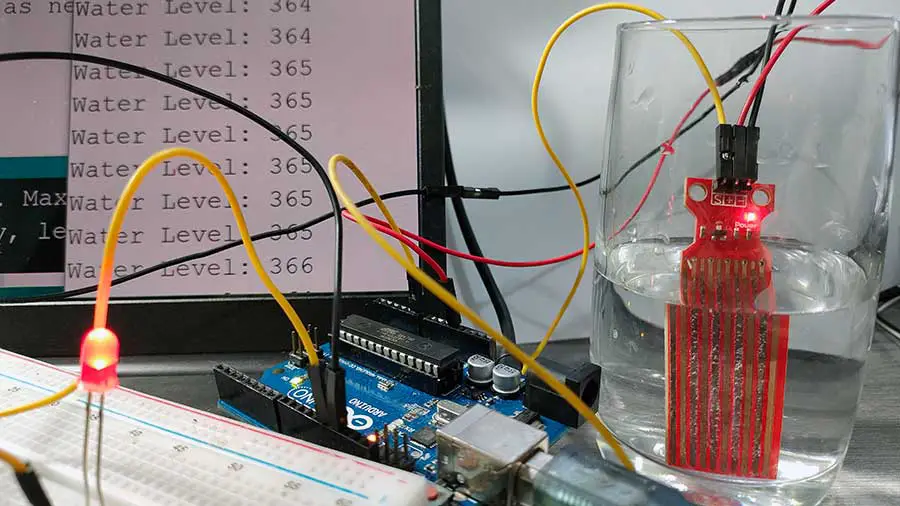
Once the code is uploaded, open the Serial Monitor from the Arduino IDE to see the water level readings. If the water level rises above the threshold, the LED should light up. You can open the Serial Monitor by going to Tools->Serial Monitor or pressing Ctrl+Shift+M.
Here's a demonstration of my output:
A More Detailed Explanation of the Arduino Code
Let's break down the Arduino code line-by-line:
// Define the pins
int waterSensorPin = A0;  // Water level sensor connected to analog pin A0
int ledPin = 13;          // LED connected to digital pin 13
- int waterSensorPin = A0;: This line defines an integer variable named
waterSensorPinand assigns it to analog pin A0. This pin will be used to read data from the water level sensor. - int ledPin = 13;: This line defines a variable integer named
ledPinand assigns it to digital pin 13. This pin will be used to control an LED, which will serve as an indicator.
void setup() {
  // Initialize serial communication at 9600 bits per second
  Serial.begin(9600);
  // Initialize the LED pin as an output
  pinMode(ledPin, OUTPUT);
}
- void setup() {: This line begins the
setupfunction, which is called once when the Arduino starts. It is used to initialize settings. - Serial.begin(9600);: This line initializes serial communication at a baud rate of 9600 bits per second. This allows the Arduino to send data to the serial monitor for debugging purposes.
- pinMode(ledPin, OUTPUT);: This line sets the
ledPin(digital pin 13) as an output. This means the pin will be used to send signals (in this case, to turn the LED on or off).
void loop() {
  // Read the input on analog pin 0
  int sensorValue = analogRead(waterSensorPin);

  // Print out the value you read
  Serial.print("Water Level: ");
  Serial.println(sensorValue);
- void loop() {: This line begins the
loopfunction, which runs continuously after thesetupfunction has finished. - int sensorValue = analogRead(waterSensorPin);: This line reads the value from the
waterSensorPin(analog pin A0) and stores it in an integer variable namedsensorValue. TheanalogReadfunction returns a value between 0 and 1023, representing the analog voltage reading. - Serial.print("Water Level: ");: This line sends the string "Water Level: " to the serial monitor. It is used for debugging to label the value being printed.
- Serial.println(sensorValue);: This line sends the value of
sensorValueto the serial monitor, followed by a newline. This helps in monitoring the water level readings.
  // Check if the water level is above a threshold
  if (sensorValue > 300) {  // Adjust the threshold as necessary
    digitalWrite(ledPin, HIGH);  // Turn the LED on
  } else {
    digitalWrite(ledPin, LOW);   // Turn the LED off
  }
- if (sensorValue > 300) {: This line checks if the
sensorValueis greater than 300. The threshold value of 300 can be adjusted based on your specific requirements. - digitalWrite(ledPin, HIGH);: If the condition (
sensorValue > 300) is true, this line sets theledPin(digital pin 13) to HIGH, turning the LED on. - } else {: This line specifies an alternative block of code to execute if the condition is false.
- digitalWrite(ledPin, LOW);: If the condition is false (i.e.,
sensorValueis 300 or lower), this line sets theledPinto LOW, turning the LED off.
  // Wait for a second before taking the next reading
  delay(1000);
}
- delay(1000);: This line pauses the program for 1000 milliseconds (1 second) before the next iteration of the
loopfunction. This delay controls how frequently the water level is checked and the LED state is updated. - }: This curly brace closes the
loopfunction.
In summary, this code reads the water level sensor value continuously, prints it to the serial monitor, and lights up an LED if the water level is above a specified threshold. This setup can be used to monitor water levels and provide visual feedback when the water level is low.
Watch this YouTube video.
Practical Applications
Home Automation
Integrating a water level sensor with an Arduino in your home water tank can automate the refilling process, ensuring that you never run out of water. By connecting a relay module, you can even control a water pump to refill the tank automatically.
Agricultural Irrigation
In agriculture, maintaining the right water level is crucial for crop health. Using a water level sensor with Arduino, you can automate irrigation systems to water the plants only when necessary, conserving water and promoting plant growth.
Industrial Water Management
Industries that require large amounts of water can benefit from automated water level monitoring systems. These systems ensure that water levels are maintained within optimal ranges, preventing shortages and overflows.
Conclusion
Using a water level sensor with Arduino is an excellent way to create efficient and automated water management systems. Whether you're a DIY enthusiast or a professional, this guide provides a comprehensive overview of the setup process, detailed Arduino code, and practical applications. By following this step-by-step guide, you'll be able to monitor and control water levels effectively, saving time, resources, and effort.


