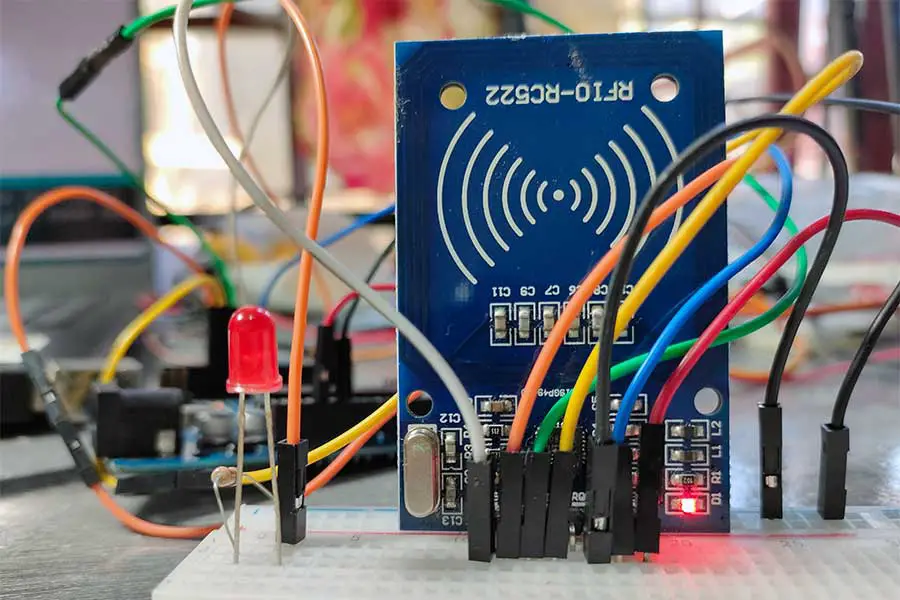
Are you looking to integrate RFID technology into your Arduino projects? The MFRC522 RFID module is a great starting point for beginners interested in creating a variety of RFID-based applications. In this guide, we'll explore how to use the MFRC522 RFID module with an Arduino. By the end of this article, you'll be able to create a simple RFID reader system and understand how RFID technology works.
What is RFID and How Does the RC522 Module Work?
RFID (Radio Frequency Identification) is a technology that uses electromagnetic fields to automatically identify and track tags attached to objects. The RC522 is a highly integrated reader/writer IC for contactless communication at 13.56 MHz. It is commonly used in projects that require reading or writing data wirelessly to a tag.
Why Use the MFRC522 RFID Module with Arduino?
RFID (Radio Frequency Identification) technology allows for the wireless transmission of data between a reader and a tag. The MFRC522 RFID module is a popular choice for Arduino projects due to its affordability, ease of use, and compatibility with various RFID tags. This setup can be used in practical applications such as access control systems, attendance systems, and inventory management.
Practical Applications of RFID with Arduino
The RFID RC522 module can be used in various practical applications, including:
- Access Control Systems: Secure your home or office by granting access only to authorized RFID tags.
- Attendance Systems: Track employee or student attendance by scanning RFID cards.
- Inventory Management: Automate your inventory tracking process by scanning RFID-tagged items.
Getting Started with the RFID RC522 Module and Arduino
Required Components
To follow along with this tutorial, you will need:
- Arduino Uno (or any compatible Arduino board)
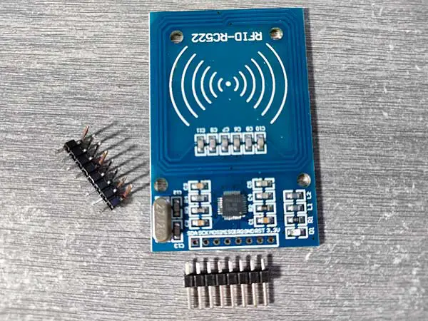
- RFID RC522 module
- RFID tags (cards or key fobs)
- Jumper wires
- Breadboard
- LED
- 220 ohm resistor for LED
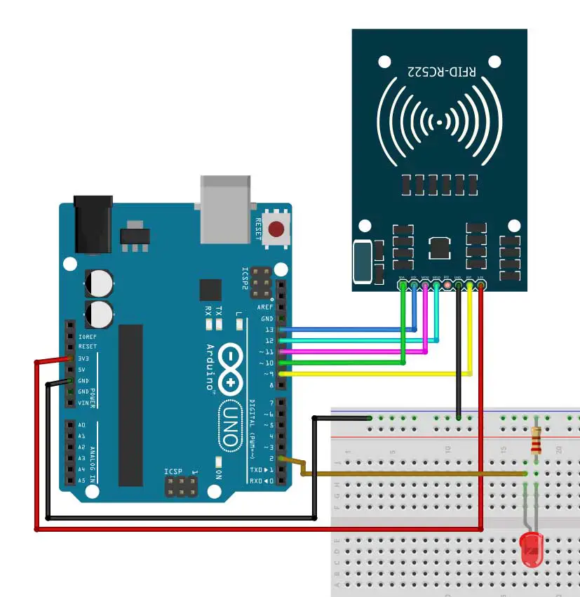
Wiring the RFID RC522 Module to Arduino
Here’s how to connect the RFID RC522 module to your Arduino:
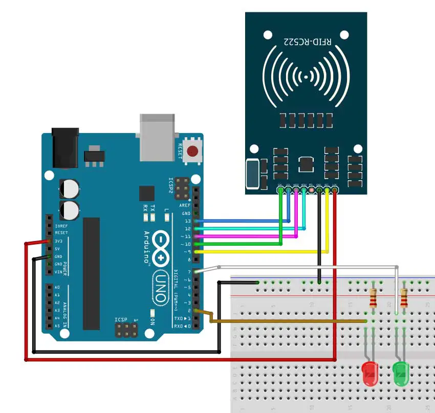
| RFID RC522 Pin | Arduino Pin |
|---|---|
| VCC | 3.3V |
| RST | Digital Pin 9 |
| GND | GND |
| MISO | Digital Pin 12 |
| MOSI | Digital Pin 11 |
| SCK | Digital Pin 13 |
| SDA (SS) | Digital Pin 10 |
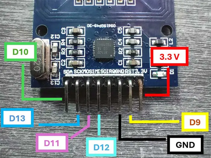
This is the breadboard circuit:
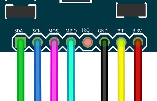
And here is a closeup of the pinouts:
Installing the Required Libraries
Before we dive into the code, you need to install the MFRC522 library. This library provides an easy way to interface with the RC522 module.
- Open the Arduino IDE.
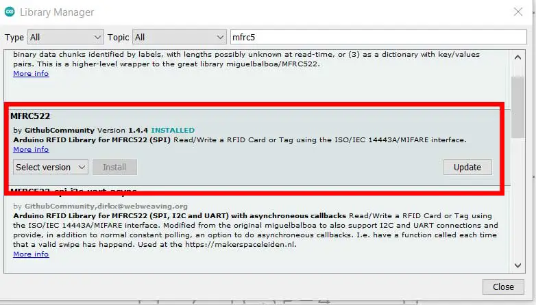
- Go to Sketch > Include Library > Manage Libraries.
- Search for "MFRC522" and install the library by GithubCommunity.
Or, you may also download the library found at the end of this article. Better yet, you may download it here:
If you want, you can download it from Github.
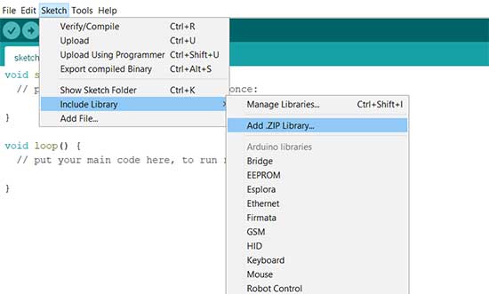
To install the library, click Sketch->Include Library->Add .ZIP Library...
PROJECT 1: RFID READER
Arduino Code for RFID RC522
Below is the Arduino code to read the UID of an RFID tag. This code will print the UID of the tag to the Serial Monitor when a tag is brought close to the reader.
#include <SPI.h>
#include <MFRC522.h>


#define SS_PIN 10
#define RST_PIN 9
MFRC522 myRFID(SS_PIN, RST_PIN);   // Create MFRC522 instance.

int pinLED=2;

void setup()
{
  Serial.begin(9600);   // Initiate a serial communication
  SPI.begin();      // Initiate  SPI bus
  myRFID.PCD_Init();   // Initiate MFRC522
  Serial.println("Please scan your RFID card...");
  Serial.println();
  pinMode(pinLED, OUTPUT);
}
void loop()
{
  // Wait for RFID cards to be scanned
  if ( ! myRFID.PICC_IsNewCardPresent())
  {

    return;
  }
  // an RFID card has been scanned but no UID
  if ( ! myRFID.PICC_ReadCardSerial())
  {

    return;
  }
  //Show UID on serial monitor
  digitalWrite(pinLED,HIGH);
  Serial.print("USER ID tag :");
  String content= "";

  for (byte i = 0; i < myRFID.uid.size; i++)
  {
     Serial.print(myRFID.uid.uidByte[i] < 0x10 ? " 0" : " ");
     Serial.print(myRFID.uid.uidByte[i], HEX);
     content.concat(String(myRFID.uid.uidByte[i] < 0x10 ? " 0" : " "));
     content.concat(String(myRFID.uid.uidByte[i], HEX));
  }
  delay(1000);
  digitalWrite(pinLED,LOW);
  Serial.println();
}
This is my output:
Code Explanation
Libraries and Definitions
#include <SPI.h>
#include <MFRC522.h>
Purpose: Includes the SPI and MFRC522 libraries required to communicate with the RFID reader.
#define SS_PIN 10
#define RST_PIN 9
MFRC522 myRFID(SS_PIN, RST_PIN);   // Create MFRC522 instance.
Purpose: Defines the Slave Select (SS) pin and the Reset (RST) pin used for the RFID reader. Creates an instance of the MFRC522 class called myRFID with these pins.
int pinLED = 2;
Purpose: Defines the pin number for an LED, which will be used to indicate when an RFID card is scanned.
Setup Function
void setup()
{
  Serial.begin(9600);   // Initiate a serial communication
  SPI.begin();      // Initiate SPI bus
  myRFID.PCD_Init();   // Initiate MFRC522
  Serial.println("Please scan your RFID card...");
  Serial.println();
  pinMode(pinLED, OUTPUT);
}
Purpose: This function runs once when the Arduino starts up. It sets up the initial configurations.
Serial.begin(9600);: Starts serial communication at a baud rate of 9600.SPI.begin();: Initializes the SPI bus.myRFID.PCD_Init();: Initializes the MFRC522 RFID reader.Serial.println("Please scan your RFID card...");: Prints a message to the Serial Monitor prompting the user to scan an RFID card.pinMode(pinLED, OUTPUT);: Sets the LED pin (pin 2) as an output.
Loop Function
// Wait for RFID cards to be scanned
if (!myRFID.PICC_IsNewCardPresent())
{
  return;
}
// an RFID card has been scanned but no UID
if (!myRFID.PICC_ReadCardSerial())
{
  return;
}
-
if (!myRFID.PICC_IsNewCardPresent()):- Purpose: Checks if a new RFID card is present near the RFID reader.
- Explanation:
myRFID.PICC_IsNewCardPresent(): This function from the MFRC522 library checks if a new RFID card is within the reader's range.!: The NOT operator inverts the result. IfPICC_IsNewCardPresent()returnsfalse(meaning no new card is present), the condition!myRFID.PICC_IsNewCardPresent()will betrue, and the code inside theifblock will execute.
- Outcome: If no new card is present, the code inside the
ifblock runs, which isreturn;. This causes theloop()function to exit early and start the next iteration, continuously checking for new cards.
-
return;:- Purpose: Exits the current iteration of the
loop()function. - Explanation: If no new RFID card is detected, this
return;statement causes theloop()function to end its current iteration immediately. The next iteration ofloop()will then begin, starting the card detection process again.
- Purpose: Exits the current iteration of the
-
if (!myRFID.PICC_ReadCardSerial()):- Purpose: Checks if the detected RFID card's UID can be read successfully.
- Explanation:
myRFID.PICC_ReadCardSerial(): This function attempts to read the UID (Unique Identifier) of the detected RFID card.!: The NOT operator inverts the result. IfPICC_ReadCardSerial()returnsfalse(meaning the UID could not be read), the condition!myRFID.PICC_ReadCardSerial()will betrue, and the code inside theifblock will execute.
- Outcome: If the UID cannot be read, the code inside the
ifblock runs, which isreturn;. This causes theloop()function to exit early and start the next iteration, continually attempting to read the UID of any detected card.
-
return;:- Purpose: Exits the current iteration of the
loop()function. - Explanation: If the RFID card's UID could not be read, this
return;statement causes theloop()function to end its current iteration immediately. The next iteration ofloop()will then begin, starting the card detection and reading process again.
- Purpose: Exits the current iteration of the
These two if statements ensure that the RFID reader is continuously checking for new cards and only proceeds if a new card is detected and its UID can be read successfully. If either condition fails (no new card or unable to read UID), the loop() function exits early and starts a new iteration, maintaining an efficient and responsive RFID scanning loop.
// Show UID on serial monitor
digitalWrite(pinLED, HIGH);
Serial.print("USER ID tag :");
String content = "";

for (byte i = 0; i < myRFID.uid.size; i++)
{
  Serial.print(myRFID.uid.uidByte[i] < 0x10 ? " 0" : " ");
  Serial.print(myRFID.uid.uidByte[i], HEX);
  content.concat(String(myRFID.uid.uidByte[i] < 0x10 ? " 0" : " "));
  content.concat(String(myRFID.uid.uidByte[i], HEX));
}
delay(1000);
digitalWrite(pinLED, LOW);
Serial.println();
This part of the code is responsible for displaying the UID (Unique Identifier) of the scanned RFID card on the Serial Monitor and controlling an LED to indicate the process visually.
-
digitalWrite(pinLED, HIGH);:- Purpose: Turns on the LED.
- Explanation: Sets the
pinLED(pin 2) to HIGH, which supplies voltage to the LED, turning it on. This indicates that a card is being processed.
-
Serial.print("USER ID tag :");:- Purpose: Prints a label to the Serial Monitor.
- Explanation: This line sends the string "USER ID tag :" to the Serial Monitor, indicating that the following output will be the UID of the RFID card.
-
String content = "";:- Purpose: Initializes an empty string to store the UID.
- Explanation: This variable will be used to concatenate the UID bytes and form a complete UID string.
-
for (byte i = 0; i < myRFID.uid.size; i++):- Purpose: Loops through each byte of the UID.
- Explanation: This loop iterates over each byte of the UID stored in
myRFID.uid.uidByte[].
-
delay(1000);:- Purpose: Introduces a delay of 1000 milliseconds (1 second).
- Explanation: This line pauses the execution of the program for 1 second, providing a brief delay before turning off the LED.
-
digitalWrite(pinLED, LOW);:- Purpose: Turns off the LED.
- Explanation: Sets the
pinLEDto LOW, which stops supplying voltage to the LED, turning it off.
-
Serial.println();:- Purpose: Prints a newline to the Serial Monitor.
- Explanation: This line sends a newline character to the Serial Monitor, ensuring the next output starts on a new line.
To summarize:
This segment of code handles the process of reading and displaying the UID of an RFID card. When a card is detected and its UID is read, the code:
- Turns on an LED to indicate a card is being processed.
- Prints the label "USER ID tag :" to the Serial Monitor.
- Iterates through each byte of the UID, prints each byte in hexadecimal format with a leading zero if necessary, and concatenates each byte to a
contentstring. - Waits for 1 second.
- Turns off the LED.
- Prints a newline to the Serial Monitor.
PROJECT 2: RFID Access Control System
Watch the making of this project here:
This project uses an RFID reader with an Arduino to scan RFID cards, print their UIDs to the Serial Monitor and whether they are denied or granted access, and control LEDs to indicate access status.
I added an LED to the previous breadboard circuit:
Arduino Code
We will just modify our existing above to include an access control feature. Here is the code:
#include <SPI.h>
#include <MFRC522.h>

#define SS_PIN 10
#define RST_PIN 9
MFRC522 myRFID(SS_PIN, RST_PIN);   // Create MFRC522 instance.

int pinLED=2;
int pinLED2=7;

void setup()
{
  Serial.begin(9600);   // Initiate a serial communication
  SPI.begin();      // Initiate  SPI bus
  myRFID.PCD_Init();   // Initiate MFRC522
  Serial.println("Please scan your RFID card...");
  Serial.println();
  pinMode(pinLED, OUTPUT);
  pinMode(pinLED2, OUTPUT);
}
void loop()
{
  // Wait for RFID cards to be scanned
  if ( ! myRFID.PICC_IsNewCardPresent())
  {

    return;
  }
  // an RFID card has been scanned but no UID
  if ( ! myRFID.PICC_ReadCardSerial())
  {

    return;
  }
  //Show UID on serial monitor
  digitalWrite(pinLED,HIGH);
  Serial.print("USER ID tag :");
  String content= "";
  for (byte i = 0; i < myRFID.uid.size; i++)
  {
     Serial.print(myRFID.uid.uidByte[i] < 0x10 ? " 0" : " ");
     Serial.print(myRFID.uid.uidByte[i], HEX);
     content.concat(String(myRFID.uid.uidByte[i] < 0x10 ? " 0" : " "));
     content.concat(String(myRFID.uid.uidByte[i], HEX));
  }
  delay(500);
  digitalWrite(pinLED,LOW);
  Serial.println();
 // Serial.print("Message : ");
  content.toUpperCase();
  if (content.substring(1) == "7B C0 AD 21") //change here the UID of the card/cards that you want to give access
  {
    Serial.println("Access Granted!");
    digitalWrite(pinLED2,HIGH);
    Serial.println();
    delay(2000);
    digitalWrite(pinLED2,LOW);
  }

 else   {
    Serial.println("Access Denied!");
    delay(2000);
  }
}
This is my output:
Code Explanation
Since our code is very similar to the previous one, let's dive directly into the newly added part of our code:
content.toUpperCase();
if (content.substring(1) == "7B C0 AD 21") //change here the UID of the card/cards that you want to give access
{
  Serial.println("Access Granted!");
  digitalWrite(pinLED2, HIGH);
  Serial.println();
  delay(2000);
  digitalWrite(pinLED2, LOW);
}
else
{
  Serial.println("Access Denied!");
  delay(2000);
}
- Purpose: Checks if the scanned UID matches a predefined UID for granting access and controls an LED based on access status.
- Explanation:
content.toUpperCase();: Converts the UID string to uppercase.if (content.substring(1) == "7B C0 AD 21"): Checks if the UID (starting from the second character) matches the predefined UID ("7B C0 AD 21"). Adjust this UID to match your specific cards.- Access Granted: If the UID matches:
Serial.println("Access Granted!");: Prints "Access Granted!" to the Serial Monitor.digitalWrite(pinLED2, HIGH);: Turns on the second LED to indicate access granted.delay(2000);: Keeps the LED on for 2 seconds.digitalWrite(pinLED2, LOW);: Turns off the second LED.
- Access Denied: If the UID does not match:
Serial.println("Access Denied!");: Prints "Access Denied!" to the Serial Monitor.delay(2000);: Waits for 2 seconds.
- Access Granted: If the UID matches:
To summarize:
This Arduino sketch sets up an RFID reader and two LEDs. It continuously checks for RFID cards, reads their UIDs, and displays the UIDs on the Serial Monitor. Depending on the UID, it turns on a second LED to indicate whether access is granted or denied. This setup is useful for access control systems where specific RFID cards are authorized to access certain areas or devices.
Conclusion
Integrating the RFID RC522 module with Arduino opens up a world of possibilities for your projects. Whether you're looking to create a secure access control system, automate attendance tracking, or streamline inventory management, this guide provides the essential knowledge and code to get you started. By following the steps outlined above, you’ll be able to successfully read RFID tags with your Arduino and begin exploring more advanced applications.
Remember to experiment with the code and customize it to fit your specific needs. The possibilities are endless when you combine RFID technology with the versatility of Arduino. Happy coding!


