Are you looking to add precise control to your robotics project using a joystick and a servo motor? This article is your ultimate guide on how to control a servo motor with a joystick and Arduino. Whether you're building a robotic arm, a pan-tilt camera mount, or a remote-controlled vehicle, understanding how to interface a joystick with a servo motor using Arduino will significantly enhance your project's functionality and precision.
Table of Contents
- Introduction
- Required Components
- Wiring the Circuit
- Arduino Code and Explanation
- Practical Applications
- Troubleshooting Tips
- Conclusion
Introduction
Using a joystick to control a servo motor with Arduino can open up numerous possibilities in your projects. For instance, you could create a custom robotic arm that mimics your hand movements or develop a camera system that tracks objects smoothly. This tutorial will walk you through the entire process, from setting up your components to writing and understanding the Arduino code that makes it all work.
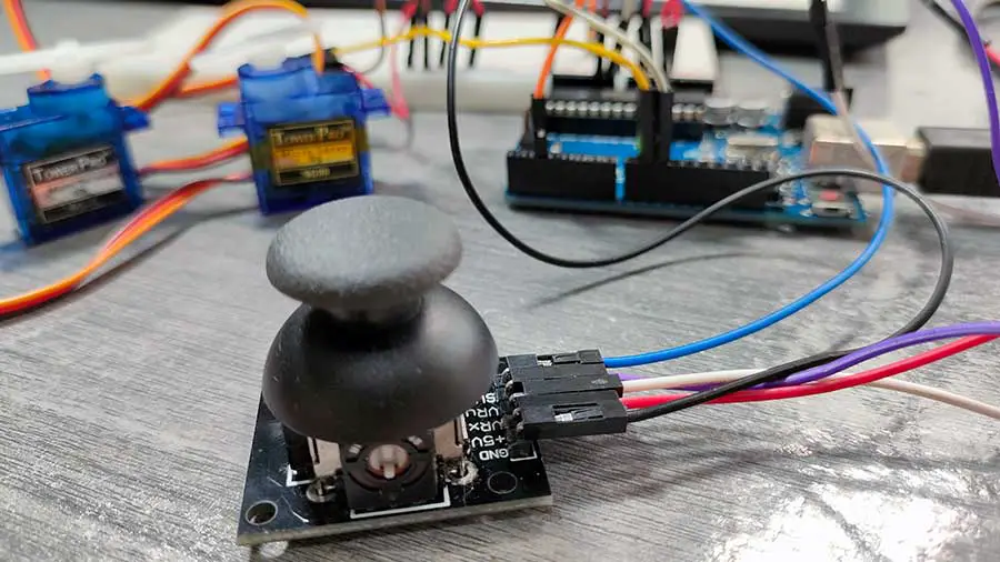
Here's what you can do with a joystick and 2 servo motors:
Why Use a Joystick with a Servo Motor?
A joystick provides an intuitive way to control the movements of a servo motor. By simply moving the joystick, you can achieve precise control over the servo's position, which is ideal for applications requiring fine motor control. This setup is particularly useful in robotics, remote-controlled systems, and interactive projects where user input is essential.
Required Components
To get started, you will need the following components:
- Arduino Uno or any compatible board
- Joystick module
- Servo motor
- Breadboard and jumper wires
- Power supply (if needed)
- 10k ohm resistor (brown-black-orange)
PROJECT 1: Getting the Joystick Values
Wiring the Circuit
Before we start with anything else, it is good to check if our joystick is working. This project will display the values of the X-axis and Y-axis of the joystick on the Serial Monitor. Here's how to connect the joystick to the Arduino.
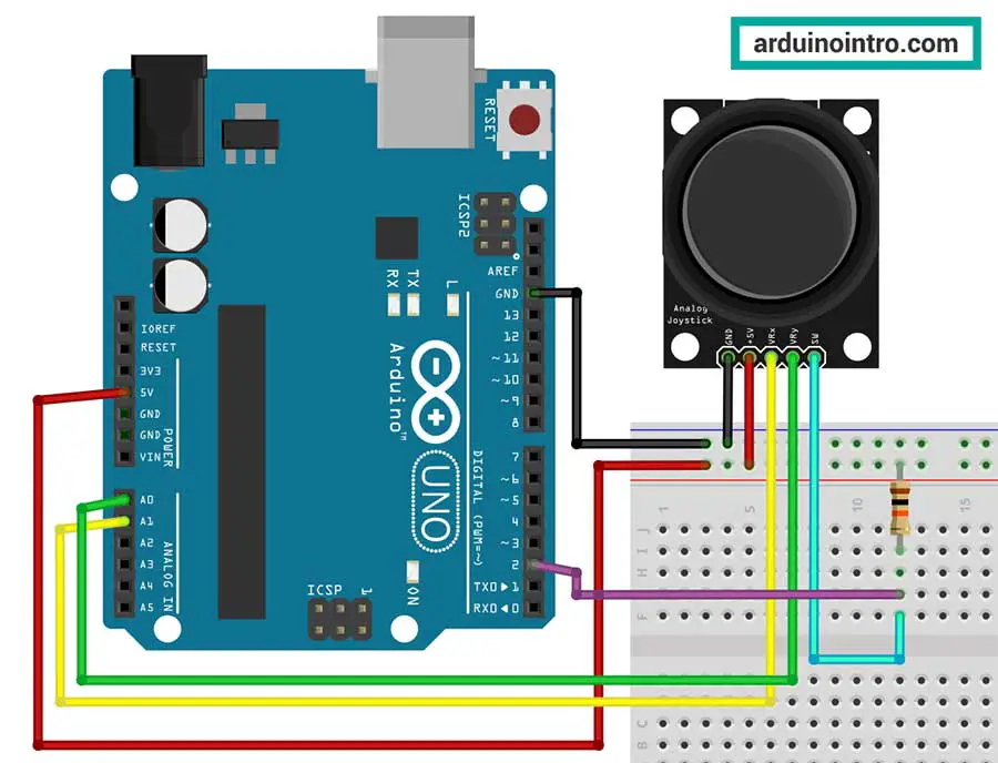
Joystick Connections:
-
- VCC to 5V on Arduino
- GND to GND on Arduino
- VRx to Analog pin A1 on Arduino
- VRy to Analog pin A0 on Arduino
- SW (switch) to Digital pin 2 on Arduino passing through a 10k ohm resistor
Arduino Code and Explanation
Below is the Arduino code that reads the joystick input values.
//display the joystick value on
//the screen

int joyXPin= A1; // X - AXIS INPUT PIN
int joyYPin = A0; // Y - AXIS INPUT PIN
int buttonPin = 2; // PUSH BUTTON
int x_val, y_val, button_val;

void setup ()
{
  Serial.begin (9600);
  pinMode (buttonPin, INPUT);
}
void loop ()
{
  //READING THE VALUE
  x_val = analogRead(joyXPin);
  y_val = analogRead(joyYPin);
  button_val = digitalRead(buttonPin);

  //PRINTING THE OUTPUT VALUE
  Serial.print("Joystick X: ");
  Serial.println (x_val);

  Serial.print ("Joystick Y:");
  Serial.println (y_val);

  Serial.print("Button IS: ");
  if (button_val == 0){
    Serial.println ("NOT PRESSED");
  }
  else{
    Serial.println ("PRESSED");
  }
  Serial.println ("");
  delay (1000);
}
Here's my output:
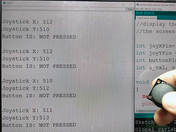
Always check the joystick values:
Step-by-Step Explanation of the Code
Variable Declaration:
int joyXPin = A1;    // X - AXIS INPUT PIN
int joyYPin = A0;    // Y - AXIS INPUT PIN
int buttonPin = 10;  // PUSH BUTTON
int x_val, y_val, button_val;
joyXPin,joyYPin, andbuttonPinstore the pin numbers for the X-axis, Y-axis, and pushbutton, respectively.x_val,y_val, andbutton_valwill store the readings from the analog pins and the digital pin, respectively.
Setup Function:
void setup() {
  Serial.begin(9600);      // Initializes serial communication at 9600 baud rate
  pinMode(buttonPin, INPUT);  // Sets buttonPin as INPUT
}
Serial.begin(9600);initializes serial communication with a baud rate of 9600.pinMode(buttonPin, INPUT);configures the buttonPin as an input pin.
Loop Function:
void loop() {
  x_val = analogRead(joyXPin);   // Reads the analog input from the X-axis joystick
  y_val = analogRead(joyYPin);   // Reads the analog input from the Y-axis joystick
  button_val = digitalRead(buttonPin);  // Reads the digital input from the push button

  // Prints the values to the Serial Monitor
  Serial.print("Joystick X: ");
  Serial.println(x_val);

  Serial.print("Joystick Y: ");
  Serial.println(y_val);

  Serial.print("Button IS: ");
  if (button_val == 0) {
    Serial.println("NOT PRESSED");
  } else {
    Serial.println("PRESSED");
  }
  Serial.println("");   // Adds a blank line for readability

  delay(1000);   // Delays execution for 100 milliseconds
}
- The
loop()function continuously reads and prints the values of the X-axis and Y-axis joysticks and the push button. analogRead(joyXPin);reads the analog voltage from the X-axis joystick pin and assigns it tox_val.analogRead(joyYPin);reads the analog voltage from the Y-axis joystick pin and assigns it toy_val.digitalRead(buttonPin);reads the digital state (HIGH or LOW) from the push button pin and assigns it tobutton_val.- The values are then printed to the Serial Monitor with appropriate labels.
- If the button is pressed (
button_valis 0), it prints "NOT PRESSED". Otherwise, it prints "PRESSED". Adjust for the value of the button, in your case, it could be 1 not 0. delay(1000);adds a small delay of 1000 milliseconds to stabilize the readings and prevent rapid flickering on the Serial Monitor.
PROJECT 2: Controlling Servo Motors With a Joystick
Wiring the Circuit
Here's how to connect the components:
-
Joystick Connections:
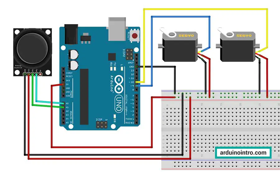
- VCC to 5V on Arduino
- GND to GND on Arduino
- VRx to Analog pin A1 on Arduino
- VRy to Analog pin A0 on Arduino
-
Servo Motor Connections:
- VCC to 5V on Arduino (or an external power source if required)
- GND to GND on Arduino
- Signal to PWM pin (example: digital pin 9) on Arduino
This is the complete breadboard circuit:
Arduino Code and Explanation
Now that we know the values of our joystick, we will modify our code to include the servo motors. Below is the Arduino code that reads the joystick input and controls the servo motor accordingly.
#include <Servo.h>
Servo s1;
Servo s2;

int ps1=9,ps2=10;
int joyXPin= A1; // X - AXIS INPUT PIN
int joyYPin = A0; // Y - AXIS INPUT PIN
int x_val,y_val;
int angle1=90,angle2=90;

void setup() {
  s1.attach(ps1);
  s2.attach(ps2);
}

void loop() {
  x_val=analogRead(joyXPin);
  y_val=analogRead(joyYPin);

  if(x_val<=100){
    angle1--;
    angle1=constrain(angle1,10,170);
    s1.write(angle1);
    delay(15);
  }
  if(x_val>=900){
    angle1++;
    angle1=constrain(angle1,10,170);
    s1.write(angle1);
    delay(15);
  }

  if(y_val<100){
    angle2++;
    angle2=constrain(angle2,10,170);
    s2.write(angle2);
    delay(15);
  }
 if(y_val>900){
    angle2--;
    angle2=constrain(angle2,10,170);
    s2.write(angle2);
    delay(15);
  }
}
Step-by-Step Explanation of the Code
Including the Servo Library and Declaring Servo Objects:
#include <Servo.h>
Servo s1;
Servo s2;
- The
#include <Servo.h>directive includes the Servo library, necessary for servo motor control. Servo s1;andServo s2;declare two Servo objects,s1ands2, which will control the servo motors.
Pin and Variable Initialization:
int ps1 = 9, ps2 = 10;  // Pin numbers for the servo motors
int joyXPin = A1;       // X-axis input pin
int joyYPin = A0;       // Y-axis input pin
int x_val, y_val;       // Variables to store analog input values
int angle1 = 90, angle2 = 90;  // Initial angles for servo motors
ps1andps2store the pin numbers for the servo motors.joyXPinandjoyYPinstore the analog input pin numbers for the X and Y axes of the joystick.x_valandy_valare variables to store the analog readings from the X and Y axes of the joystick.angle1andangle2store the initial angles fors1ands2servo motors, respectively.
Setup Function:
void setup() {
  s1.attach(ps1);  // Attaching servo s1 to pin ps1 (pin 9)
  s2.attach(ps2);  // Attaching servo s2 to pin ps2 (pin 10)
}
The setup() function initializes the serial communication and attaches s1 and s2 servo motors to their respective pins.
Loop Function:
void loop() {
  x_val = analogRead(joyXPin);  // Read analog input from X-axis of the joystick
  y_val = analogRead(joyYPin);  // Read analog input from Y-axis of the joystick

  if (x_val <= 100) {
    angle1--;  // Decrease angle1
    angle1 = constrain(angle1, 10, 170);  // Constrain angle1 within the range of 10 to 170 degrees
    s1.write(angle1);  // Set the angle of servo s1
    delay(15);  // Delay for stability
  }
  if (x_val >= 900) {
    angle1++;  // Increase angle1
    angle1 = constrain(angle1, 10, 170);  // Constrain angle1 within the range of 10 to 170 degrees
    s1.write(angle1);  // Set the angle of servo s1
    delay(15);  // Delay for stability
  }

  if (y_val < 100) {
    angle2++;  // Increase angle2
    angle2 = constrain(angle2, 10, 170);  // Constrain angle2 within the range of 10 to 170 degrees
    s2.write(angle2);  // Set the angle of servo s2
    delay(15);  // Delay for stability
  }
  if (y_val > 900) {
    angle2--;  // Decrease angle2
    angle2 = constrain(angle2, 10, 170);  // Constrain angle2 within the range of 10 to 170 degrees
    s2.write(angle2);  // Set the angle of servo s2
    delay(15);  // Delay for stability
  }
}
- The
loop()function continuously reads the analog input values from the X and Y axes of the joystick. - Based on the analog readings, it adjusts the angles of the servo motors
s1ands2. - If the X-axis value (
x_val) is less than or equal to 100, it decreasesangle1(servo s1's angle) by one and constrains it within the range of 10 to 170 degrees. It then sets the new angle ofs1usings1.write(angle1). - If the X-axis value is greater than or equal to 900, it increases
angle1by one and performs the same constraints and angle setting fors1. - Similar operations are performed for the Y-axis value (
y_val) to adjust the angle ofs2. delay(15)is added after each angle adjustment for stability and smooth operation of the servo motors.
More on the constrain() function
In Arduino, the constrain() function is used to limit a value to within a specified range. Its purpose is to ensure that a variable stays within certain boundaries, preventing it from exceeding minimum or maximum limits.
The constrain() function takes three arguments:
- Value: The value that needs to be constrained.
- Lower Bound: The minimum value that the variable can take.
- Upper Bound: The maximum value that the variable can take.
Here's the syntax of the constrain() function:
constrain(value, lowerBound, upperBound);
The constrain() function works as follows:
- If the
valueis less than thelowerBound, it returns thelowerBound. - If the
valueis greater than theupperBound, it returns theupperBound. - If the
valueis within the specified range, it returns thevalueunchanged.
To apply the concept to our code:
angle1 = constrain(angle1, 10, 170);
- The
constrain()function is used here to ensure thatangle1remains within a specified range. - It takes three arguments:
angle1: The value that needs to be constrained.10: The lower bound of the range (inclusive).170: The upper bound of the range (inclusive).
- If
angle1is less than 10,constrain()will return 10. Ifangle1is greater than 170, it will return 170. Otherwise, it will returnangle1itself if it falls within the range. - The result of
constrain()is assigned back toangle1, ensuring thatangle1is adjusted to stay within the specified range.
Purpose:
The primary purpose of the constrain() function is to ensure that a variable remains within a defined range, which can be essential for various applications, such as:
-
Sensor Readings: When reading sensor values, such as analog inputs from sensors or potentiometers, the data may fluctuate beyond the desired range due to noise or environmental factors. Using
constrain()ensures that the sensor readings remain within a valid range. -
Servo Motor Control: Servo motors typically have limited range of motion. By using
constrain(), you can ensure that the angles provided to the servo motors stay within the permissible range, preventing them from attempting to move beyond their physical limits.
Overall, the constrain() function adds robustness to Arduino programs by preventing unexpected behavior that could arise from values exceeding specified boundaries, contributing to the reliability and stability of the system.
Practical Applications
Robotic Arm Control
Using a joystick to control a servo motor can be particularly useful in creating a robotic arm. You can program the joystick to control multiple servos, enabling complex movements and tasks. For instance, moving the joystick forward and backward could control the arm's extension, while left and right movements could rotate the base.
Pan-Tilt Camera System
Another practical application is a pan-tilt camera system. By using two servos and a joystick, you can control the horizontal and vertical movement of the camera. This setup is ideal for surveillance systems, wildlife photography, and interactive art installations.
Troubleshooting Tips
- Servo Jitter:
- If your servo motor jitters or makes erratic movements, ensure that it is receiving adequate power. You may need to use an external power supply.
- You may also have faulty jumper wires. I changed my jumper wires twice while making this project until it finally worked!
- Joystick Calibration: If the servo does not respond accurately to joystick movements, try recalibrating the joystick by adjusting the mapping values in the code.
- Serial Monitor: Utilize the serial monitor to debug and verify the values read from the joystick. This can help identify any issues with the analog readings.
Conclusion
Controlling a servo motor with a joystick and Arduino is a powerful way to bring interactive and precise control to your projects. By following this guide, you now have the knowledge to wire your components, write the necessary Arduino code, and apply this setup to practical applications. Whether you're working on a robotic arm, a pan-tilt camera, or any other project requiring fine control, this guide serves as a valuable resource.


