Made by: Daryl Nikkoli C. Belga
For this project, we are going to make a Table Lamp. A Table Lamp that can be used for decoration or a bedside lamp or an office desk lamp. This Lamp is created out of recyclable materials like cardboard boxes from groceries. My goal is to show that everyone can make a lamp out of recyclable materials, and you can also create a design for your lamp with your own interest.
Materials
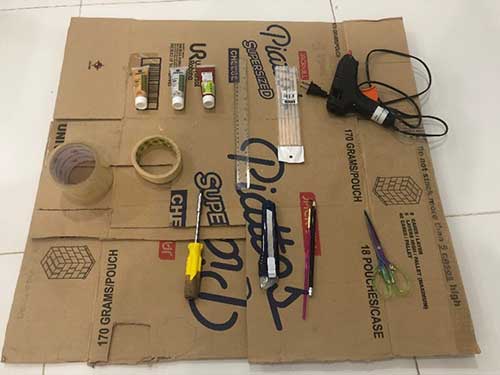
- Cardboard
- 8 LEDs (Optional: Green, Yellow, Blue, Red, Purple, Orange)
- Glue Gun
- Glue Stick
- Ruler
- Red, Silver, and Gold Acrylic Paint
- Breadboard
- Arduino Board
- Female Jump Wires
- Male Jump Wires
- Cutter
- Scissors
- Screwdriver
- Paint Brush
- Masking Tape
- Plastic Tape
- Pencil
- Pentel Pen
- Push Button
- 10k-ohm and 220-ohm Resistors
Concept
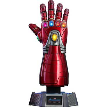
For this project, I chose the Nano Gauntlet design because I’m a huge MARVEL fan and I would also like to create a MARVEL-based decoration for my room. You can also make your own design like the Infinity Gauntlet Thanos Version or even a shoebox wall lamp. You can create any design as long it is applicable to the materials that I have mentioned.
Procedure
Making of the Nano Gauntlet:
To create the structure, I researched a D-I-Y video on “How to make a Nano Gauntlet Design out of cardboard”. Here is the reference video on “How to Make Iron Man's Nano Gauntlet from Cardboard”: https://youtu.be/XthaP3R6o-A
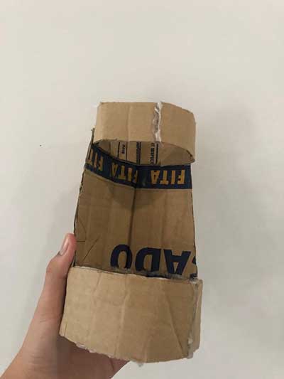
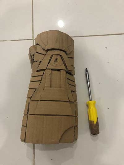
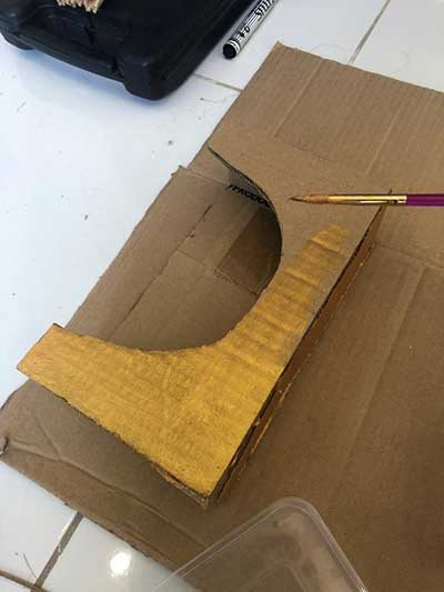
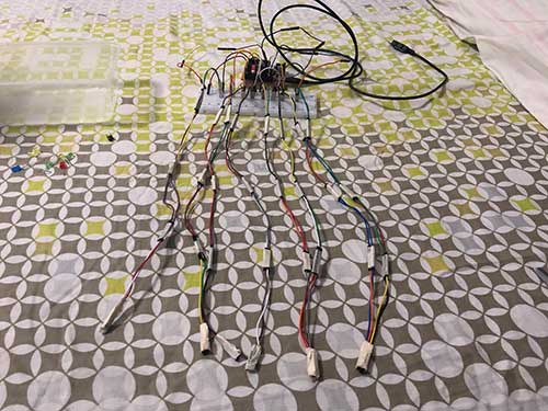
Step 1: To create the structure, I traced the cardboard using a pencil and ruler. After tracing the required parts, I start cutting and gluing the parts using glue gun.
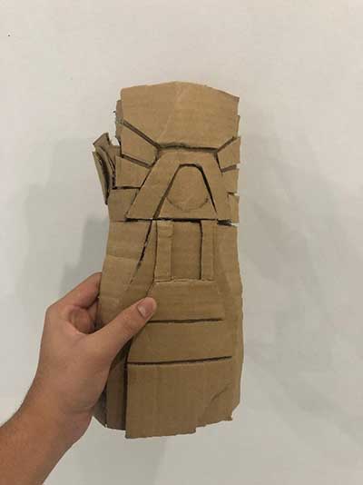
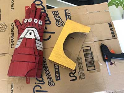
Step 2: To add designs, I traced the cardboard with the hand design template and start cutting and gluing it to the structure.
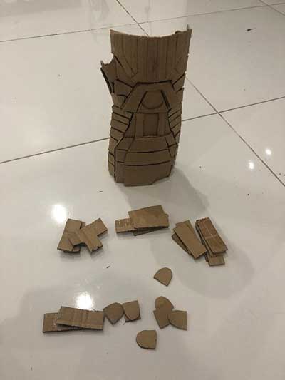
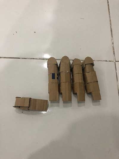
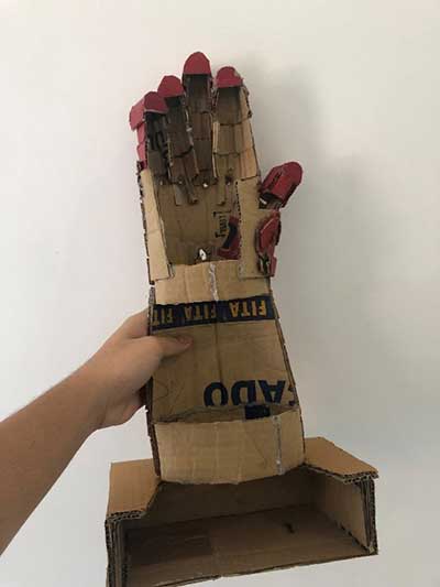
Step 3: To make the fingers, I traced the cardboard with the finger structure template and start cutting it.
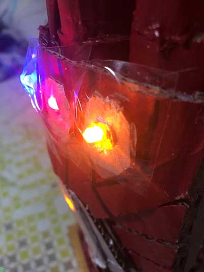
Step 4: To make the holes for the 6 Infinity Stones, I used a screwdriver to poke the structure with 6 holes.

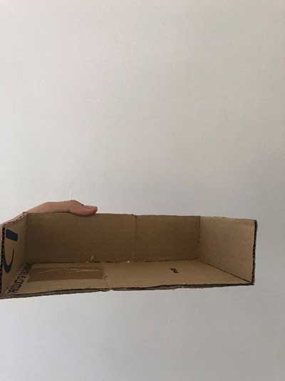
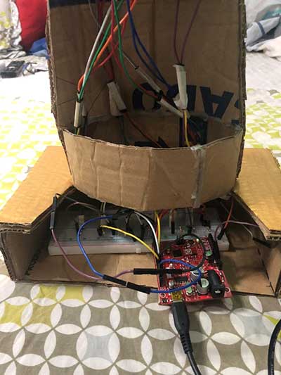
Step 5: To make the base or platform of the structure, I traced the cardboard for the parts and start cutting and gluing it to make a rectangular box-like platform. The purpose of this platform is to hide the breadboard and help the structure stand.
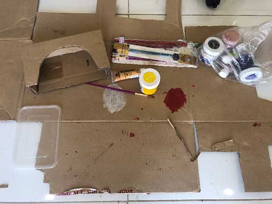
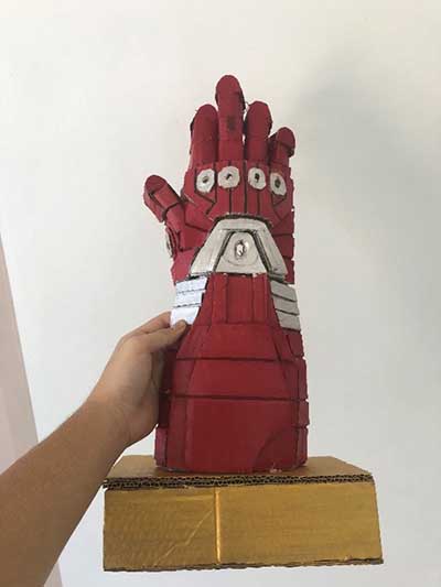
Step 6: After making the structure, platform, and the fingers, I start painting them using red, gold, and silver acrylic paints.
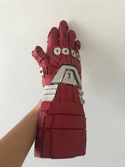
Step 7: After the paint is dry, I started gluing the structure, platform, and fingers to each other.
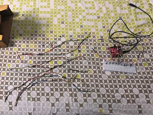
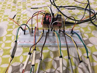
Arduino Electronics
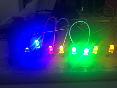
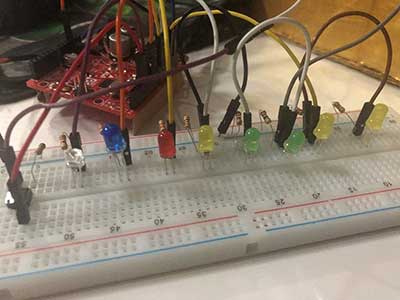
To assemble the breadboard, I made my own setup using 8 LEDs and 6 pins instead of using 8 LEDs and 4 pins setup. I used 6 pins since there are 6 Infinity Stones in the Gauntlet Design and I want to light up my lamp with six colors. I specifically used Blue, Purple, Red, Yellow, and Green LEDs to match the 6 Infinity Stones color. The pins are 3, 6, 9, 10, 11, 12.
If you wondered how I used 6 pins, I selected the Mind and Time Stone part of my structure to have 2 LEDs running at the same time while the other stones only have 1 LED running in them.
Mind Stone – 2 Yellow LEDs in the middle
Time Stone – 2 Green LEDs in the thumb
Power Stone – Purple LED in the 1st knuckle
Space Stone – Blue LED in the 2nd knuckle
Reality Stone – Red LED in the 3rd knuckle
Soul Stone – Yellow LED in the 4th knuckle
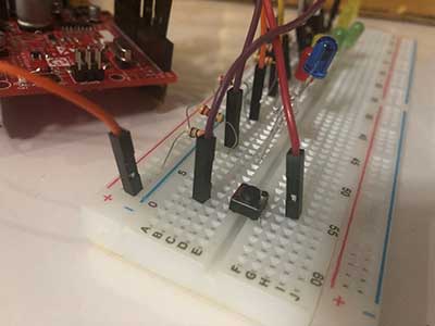
The pushbutton is accompanied by a 10k resistor and two jumper cables. The red jumper cable is the digital pin jumper cable. It is plugged in the number 2 pin. The purple jumper cable is plugged inside the 5v analog pin.
I used 32 female and male jumper wires for the LEDs connection to make it long and have a connection to the holes that I have made in the structure.
1 LED = 4 female and 4 male jumper wires
8 LEDs = 4 female jumper wires x 8 = 32 female jumper wires
4 male jumper wires x 8 = 32 male jumper wires
I also taped the jumper wires to be less confusing and secured
Arduino Sketch
For the Arduino Sketch, I made my own code for 8 LEDs 6 pins with the LED sticky switch button, and I added LED effects such as running, blinking, and fading effects. The loop will also start again from the beginning if you click the pushbutton again after the effects are done running.
/*
  The "sticky" push button
  LED turns on when pushbutton is pressed and released once.
  LED stays ON
  LED turns off when pushbutton is pressed again.
  LED stays OFF
*/

int PinButton2 = 2;
int pin3 = 3, pin6 = 6, pin9 = 9, pin10 = 10, pin11 = 11, pin12 = 12;
int val = 0;
int ledstate = LOW; //initial value


void setup() {
  pinMode(PinButton2, INPUT);
  pinMode(pin3, OUTPUT);
  pinMode(pin6, OUTPUT);
  pinMode(pin9, OUTPUT);
  pinMode(pin10, OUTPUT);
  pinMode(pin11, OUTPUT);
  pinMode(pin12, OUTPUT);
}

void loop() {
  //put your main code here to run repeatedly:
  val = digitalRead(PinButton2);
  if (val == HIGH) //button is pressed
  {

    ledstate = !ledstate; {
      digitalWrite(pin3, ledstate);
      digitalWrite(pin6, ledstate);
      digitalWrite(pin9, ledstate);
      digitalWrite(pin10, ledstate);
      digitalWrite(pin11, ledstate);
      digitalWrite(pin12, ledstate);
      delay(700);
    }
    for (int fadeValue = 0 ; fadeValue <= 255; fadeValue = fadeValue + 5) {
      analogWrite(pin3, fadeValue);
      analogWrite(pin6, fadeValue);
      analogWrite(pin9, fadeValue);
      analogWrite(pin10, fadeValue);
      analogWrite(pin11, fadeValue);
      analogWrite(pin12, fadeValue);
      delay(30);
    }
    for (int fadeValue = 255 ; fadeValue >= 0; fadeValue = fadeValue - 5) {
      analogWrite(pin3, fadeValue);
      analogWrite(pin6, fadeValue);
      analogWrite(pin9, fadeValue);
      analogWrite(pin10, fadeValue);
      analogWrite(pin11, fadeValue);
      analogWrite(pin12, fadeValue);
      delay(30);
    }
    // put your main code here, to run repeatedly:
    digitalWrite(pin3, HIGH);//it mean to give 5v(high) to pins.here ,the led will be on.
    delay(1000);
    digitalWrite(pin6, HIGH);
    delay(1000);
    digitalWrite(pin9, HIGH);
    delay(1000);
    digitalWrite(pin10, HIGH);
    delay(1000);
    digitalWrite(pin11, HIGH);
    delay(1000);
    digitalWrite(pin12, HIGH);
    delay(1000);

    digitalWrite(pin3, LOW);//it mean to give 0v(low) to pin.here, led will be off
    delay(1000);
    digitalWrite(pin6, LOW);
    delay(1000);
    digitalWrite(pin9, LOW);
    delay(1000);
    digitalWrite(pin10, LOW);
    delay(1000);
    digitalWrite(pin11, LOW);
    delay(1000);
    digitalWrite(pin12, LOW);
    delay(1000);

    digitalWrite(pin3, HIGH);//it mean to give 5v(high) to pins.here ,the led will be on.
    delay(1000);
    digitalWrite(pin6, HIGH);
    delay(1000);
    digitalWrite(pin9, HIGH);
    delay(1000);
    digitalWrite(pin10, HIGH);
    delay(1000);
    digitalWrite(pin11, HIGH);
    delay(1000);
    digitalWrite(pin12, HIGH);
    delay(1000);

    digitalWrite(pin3, HIGH);
    delay(100);
    digitalWrite(pin6, HIGH);
    delay(100);
    digitalWrite(pin9, HIGH);
    delay(100);
    digitalWrite(pin10, HIGH);
    delay(100);
    digitalWrite(pin11, HIGH);
    delay(100);
    digitalWrite(pin12, HIGH);
    delay(100);

    digitalWrite(pin3, LOW);
    delay(100);
    digitalWrite(pin6, LOW);
    delay(100);
    digitalWrite(pin9, LOW);
    delay(100);
    digitalWrite(pin10, LOW);
    delay(100);
    digitalWrite(pin11, LOW);
    delay(100);
    digitalWrite(pin12, LOW);
    delay(100);

    //start of fade-in effect
    analogWrite(pin3, 5);
    delay(30);
    analogWrite(pin6, 15);
    delay(30);
    analogWrite(pin9, 25);
    delay(30);
    analogWrite(pin10, 35);
    delay(30);
    analogWrite(pin11, 45);
    delay(30);
    analogWrite(pin12, 55);
    delay(30);


    //start of fade-out effect

    analogWrite(pin3, 255);
    delay(30);
    analogWrite(pin6, 245);
    delay(30);
    analogWrite(pin9, 235);
    delay(30);
    analogWrite(pin10, 225);
    delay(30);
    analogWrite(pin11, 215);
    delay(30);
    analogWrite(pin12, 205);
    delay(30);

    digitalWrite(pin3, HIGH);//it mean to give 5v(high) to pins.here ,the led will be on.
    delay(1000);
    digitalWrite(pin6, HIGH);
    delay(1000);
    digitalWrite(pin9, HIGH);
    delay(1000);
    digitalWrite(pin10, HIGH);
    delay(1000);
    digitalWrite(pin11, HIGH);
    delay(1000);
    digitalWrite(pin12, HIGH);
    delay(1000);

    digitalWrite(pin3, LOW);//it mean to give 0v(low) to pin.here, led will be off
    delay(1000);
    digitalWrite(pin6, LOW);
    delay(1000);
    digitalWrite(pin9, LOW);
    delay(1000);
    digitalWrite(pin10, LOW);
    delay(1000);
    digitalWrite(pin11, LOW);
    delay(1000);
    digitalWrite(pin12, LOW);
    delay(1000);

    digitalWrite(pin3, HIGH);//it mean to give 5v(high) to pins.here ,the led will be on.
    delay(1000);
    digitalWrite(pin6, HIGH);
    delay(1000);
    digitalWrite(pin9, HIGH);
    delay(1000);
    digitalWrite(pin10, HIGH);
    delay(1000);
    digitalWrite(pin11, HIGH);
    delay(1000);
    digitalWrite(pin12, HIGH);
    delay(1000);
  }
}
Assembling the Lamp
After doing all the Procedures, we can now start assembling the Lamp.
Step 1: To assemble the Lamp, I placed the breadboard on the platform with its jumper wires.
Step 2: I placed the LEDs to their respective places and used masking tape to help them stick behind the hand and to be secured.
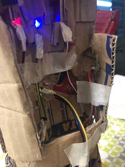
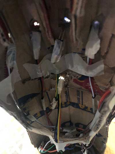
Step 3: I used plastic tape to cover the LEDs and to also add protection to the LEDs
Step 4: I plug my COM Port into my Computer, upload my code, and then click the pushbutton to run my lamp.
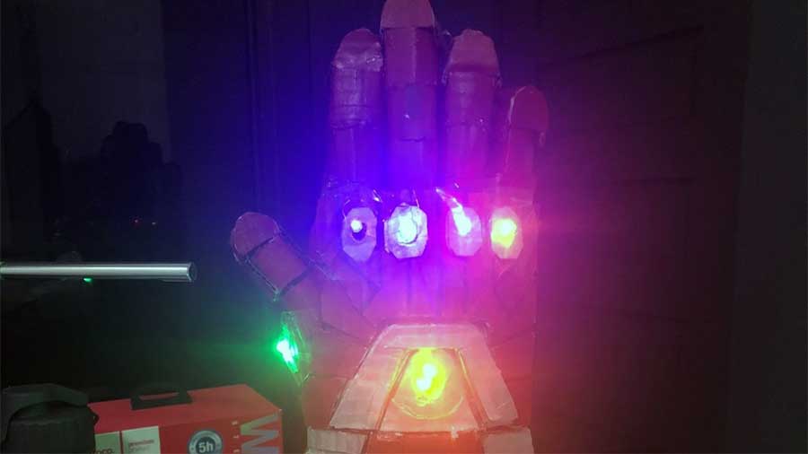
Finish Product
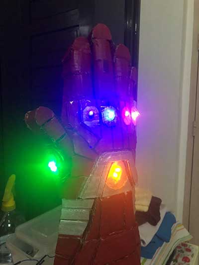
At Night:
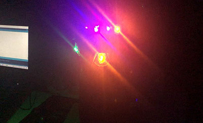
Full Loop Effect Link:
Final Thoughts
While making my product, I felt exhausted and amazed because this project is difficult to make and I need to come up with my own improvisations, it is really exhausting making this Lamp for 3 days, I also need to come up with my own code to make my LED effect creative which is also difficult, and I felt amazed after the results. I felt proud after I saw my lamp worked because I was able to make a Lamp Design out of my interest.
I felt proud because the result of my project came out way better than I expected. Seeing the Gauntlet with Infinity Stones like LEDs running with different LED effects or combinations made me feel like I was watching the Avengers Endgame Movie again. Seeing my lamp worked made me feel like I am Inevitable, and I can save half of the universe with a single snap. It was nice doing this activity because it was like a little flashback when I’m in art class. It is like a flashback because I need to revive my painting skills and I need to come up with my own creativity in designing my structure. I also need to be creative in making my led pattern combination to make my Lamp beautiful, attractive, appealing, and fun.
I realized that making this project really requires time because it is time-consuming and difficult. To conclude, this activity helped me realize that I can achieve my own goals in life if I work hard, exert my time, and effort. I am aware that I need to finish the project at a certain time, but I have decided to sacrifice timeliness over quality especially that I am passionate about this project. As one saying goes “Timeliness is an enemy of art.” – Anne Bosworth Greene.


