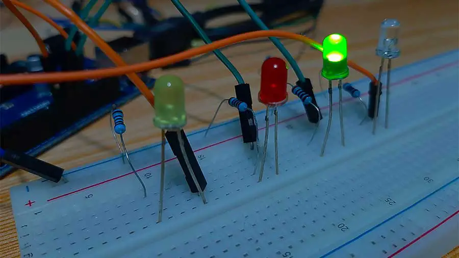
The running led effect or the led chaser effect is a popular project in Arduino. The blinking pattern produced by this effect is similar to a traffic light system, a volume level indicator, or led signage of a store. To produce this effect you need to connect more than 1 LED to your Arduino board.
This project is an upgrade from our blinking led project in that it uses more than 1 LED. In the blinking led project, we hooked up 1 LED to 1 digital pin. In this project, we will connect 4 LEDs into 4 different digital pins. In fact, with the exception of digital pins 1 and 0, we can connect 1 LED to each of the digital pins of our Arduino Uno board.
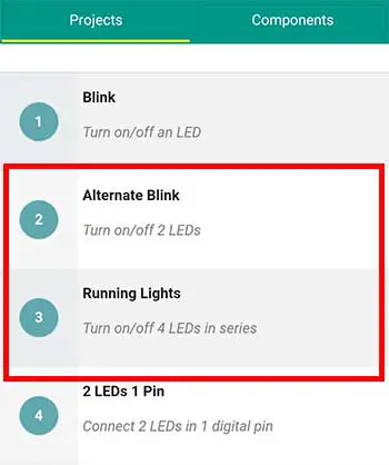
To help us make this project, we will be using again the Arduino Intro app. In this article, we will make Project 2, Alternate blink, and Project 3, the Running Lights project. The idea here is to turn on and turn off each LED separately.
PROJECT 1: Alternate Blink Effect
Let’s make the Alternate blink project first. For this, you’ll need 2 LEDs and 2 220-ohm resistors. 220-ohm resistors are colored red-red-brown.
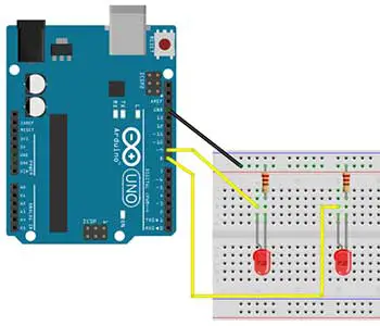
If we look at the breadboard diagram, we can see that the positive sides of the LEDs are connected on different pins. The positive side or anode of LED 1 is connected to digital pin 9. While the anode of LED 2 is connected to pin 8. The anode of LED 1 is placed in G5 and the cathode in G6. Again, you don’t have to follow this exactly as long as the anode and cathode are not directly connected. This is also true for LED 2.
Next, we place a resistor on the negative side of the LED before it connects to the Arduino board. Well, you can actually place it either on the positive or the negative side. Either way, it will still work. What we need to do is connect one end of the resistor to the negative side of the LED, and the other end should be connected to the Ground or GND of the Arduino board. We should do this for both of the LEDs.
One technique to save on jumper wires, which also lessens the clutter on our circuit, is to connect one end of a jumper wire from the GND of the Arduino and the other end to the power rails of the breadboard. When we connect the resistors to the power rails, both will now be connected to the GND of the Arduino. Again, this is just one way to make the connection. You may use another method to accomplish this. As long as the resistors on the breadboard are connected to the GND on the Arduino, everything will work out just fine.
The Alternate Blink Code
Now on to the code. Remember our objective is to turn on and turn off each of the LEDs separately. What we want is to turn on LED 1 and at the same time, turn off LED 2. And after a delay of 1 second, LED 1 will be turned off while LED 2 will be turned on. And this goes on in a loop until there is no more power supplied to the Arduino board. Here is the complete code:
/*
	Alternate Blink
		1.	Turn on LED1, turn off LED2 for
			1 second (at the same time)
		2.	Turn off LED1, turn on LED2 for
			1 second (at the same time)
		3.	Repeat
*/

  int pinA=9;
  int pinB=8;

  void setup() {
    pinMode(pinA,OUTPUT);
    pinMode(pinB,OUTPUT);

  }

  void loop() {
    //turn on pinA and turn off pinB
    digitalWrite(pinA,HIGH);
    digitalWrite(pinB,LOW);

    //wait 1 sec
    delay(1000);

    //turn off pinA and turn on pinB
    digitalWrite(pinA,LOW);
    digitalWrite(pinB,HIGH);

    //wait 1 sec
    delay(1000);
  }
First, we need to declare 2 variables for the 2 digital pins that we are using. Pin 9 is assigned to the variable pinA and pin 8 is assigned to the variable pinB.
void setup() {
    pinMode(pinA,OUTPUT);
    pinMode(pinB,OUTPUT);

  }
Next in the setup function, we simply set our 2 variables as output pins. We can do that by writing a pinmode command for each of the variables. So we have pinMode(pinA, OUTPUT); and for pinB, we write pinMode(pinB, OUTPUT); . Note that we type in a semicolon after each pinMode statement.
//turn on pinA and turn off pinB
    digitalWrite(pinA,HIGH);
    digitalWrite(pinB,LOW);

    //wait 1 sec
    delay(1000);
We turn on and turn off the LEDs inside the loop function. To turn on LED 1, we type in digitalWrite(pinA, HIGH); and to turn off LED 2, we immediately type in digitalWrite(pinB, LOW); . By writing these statements in succession, they will be executed at almost the same time. Well, LED 1 is turned on first before LED 2 is turned off, but this happens so fast that our eyes can’t see the delay.
Now, we want both LEDs to stay in their current states for 1 second. That means, LED 1 stays on for 1 second before it turns off. And LED 2 stays off for 1 second before it turns on. To do that, we simply type in delay(1000); Again, 1000 is for 1000 milliseconds or 1 second.
   //turn off pinA and turn on pinB
    digitalWrite(pinA,LOW);
    digitalWrite(pinB,HIGH);

    //wait 1 sec
    delay(1000);
  }
So after we wait for 1 second, we now turn off LED 1 by typing digitalWrite(pinA, LOW); and digitalWrite(pinB, HIGH);
We place another delay of 1 second just before the closing brace because we want the current states of the LED to stay for 1 second before the loop goes back again from the beginning.
PROJECT 2: Running Lights Effect
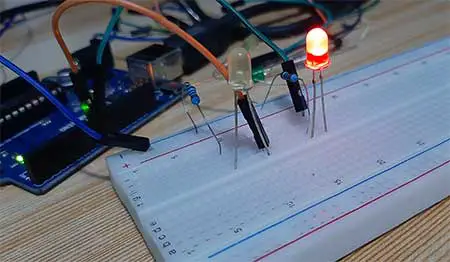
This is how easy it is to make an alternate blinking effect in Arduino. Now, let’s take this further and add two more LEDs. We want to make sure that only one LED is turned on at any given time. By turning on the next LED and turning off the previous one in succession, we can make a running lights effect.
This is Project number 3 in the Arduino Intro app which is the Running Lights project. In this project, we turn on and turn off 4 LEDs in series. Of course, we can always add more LEDs if we want. We will need 4 LEDs and 4 220-ohm resistors for this project.
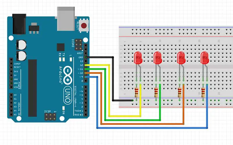
Based on the breadboard diagram, we connect the anodes of each LED to different pins. While the resistors are all connected from the cathodes of the LEDs into the power rail and finally into the GND pin of the Arduino. Note that by using the power rail, we were only able to use one jumper wire to connect all resistors to the GND pin.
Here is the complete code for the running lights effect:
	//running lights using 4 LEDs

	int pin9=9, pin10=10, pin11=11, pin12=12;


	void setup() {
		pinMode(pin9,OUTPUT);
		pinMode(pin10,OUTPUT);
		pinMode(pin11,OUTPUT);
		pinMode(pin12,OUTPUT);
	}

	void loop() {
		digitalWrite(pin12,LOW);
		digitalWrite(pin9,HIGH);
		delay(500);
		digitalWrite(pin9,LOW);
		digitalWrite(pin10,HIGH);
		delay(500);
		digitalWrite(pin10,LOW);
		digitalWrite(pin11,HIGH);
		delay(500);
		digitalWrite(pin11,LOW);
		digitalWrite(pin12,HIGH);
		delay(500);
	}
int pin9=9, pin10=10, pin11=11, pin12=12; For the code, we simply declared 4 variables, one for each of the LEDs. Note also the way we declare the variables. This is another way to declare more than one variable on a single statement. We just separate each variable name with a comma. By writing int at the beginning of the statement, all variables will have the int or the integer data type. Remember that variables of the type int can have whole numbers as their value. Finally, we end the variable declaration statement with a semicolon.
For the loop function, what we want to do is to turn an LED and at the same time, turn off the LED that was previously turned on. In this way, only 1 LED will light up at any given time.
In the first line, we turn off the last LED in the series by writing a LOW setting for pin12. And at the same time, we turn on the first LED in the series by writing a HIGH setting for pin9. To make the effect run faster, we simply write 500 milliseconds or half a second in the delay function before turning on the next led in the series. As this goes on in a loop, after the last LED which is pin12 is turned on, it will be turned off once the loop starts again because this is actually the first statement we write inside the loop function.
We can play around with the delay function to make it run slower or faster. We can even change the blinking order of LEDs. This is really a fun project, especially for those who are just starting with Arduino.


