
In this tutorial, we will learn how to control an RGB LED with Arduino. An RGB LED is a special type of light-emitting diode that can emit red, green, and blue colors independently or combine them to create various hues. With Arduino, we can easily manipulate the colors and brightness of the RGB LED to create stunning visual effects. We will walk through the process step-by-step, from wiring the components to writing the Arduino code for controlling the RGB LED.
Here's a demo:
How does the RGB LED work in Arduino?
An RGB LED (Red, Green, Blue Light Emitting Diode) is a specialized type of LED that can emit light in three primary colors: red, green, and blue. By controlling the intensity of each of these colors, you can produce a wide range of colors, including white when all three are at full intensity.
Here's how an RGB LED works with Arduino:
-
Basic Structure:
- An RGB LED contains three individual LEDs within a single package: one red, one green, and one blue.
- Each of these LEDs has a separate anode (positive terminal) and a common cathode (negative terminal) or a common anode and separate cathodes.
-
Pins:
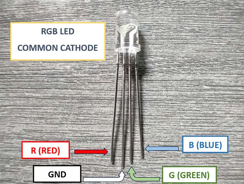
- If you have a common cathode RGB LED, one of the pins will be the cathode (usually the longest pin or one indicated by a flat edge on the package) which is connected to the common negative (-) terminal.
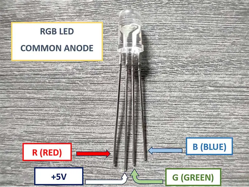
- If you have a common anode RGB LED, one of the pins will be the anode (usually the longest pin) which is connected to the common positive (+) terminal.
-
Controlling the Colors:
- To illuminate a specific color, you need to apply a voltage to the corresponding anode pin (for common anode) or cathode pin (for common cathode).
- For example, to make a red light, you apply a voltage across the red anode and the common cathode (or red cathode and common anode).
-
PWM (Pulse Width Modulation):
- Arduino can control the intensity of the LEDs by rapidly toggling them on and off. This is called PWM. It simulates an analog voltage by rapidly switching the LED on and off, effectively changing the average voltage.
- For example, if you want a dim red, you might PWM the red pin at a lower duty cycle.
-
Arduino Code:
- In your Arduino code, you define which pins are connected to the red, green, and blue anodes (or cathodes), and then you use
analogWrite()to control the intensity of each color. - For example,
analogWrite(redPin, 255)sets the red LED to full brightness.
- In your Arduino code, you define which pins are connected to the red, green, and blue anodes (or cathodes), and then you use
-
Color Mixing:
- By varying the intensity of each color, you can create a wide range of colors. For example, equal intensity of red, green, and blue results in white light. No intensity for all colors gives black (off).
-
Safety Considerations:
- It's crucial to use resistors to limit current. Without them, you could damage the LEDs or the Arduino.
-
Common Mistakes:
- Mixing up the pins can lead to unexpected behavior. Always double-check your wiring.
PROJECT 1: RGB LED
Materials Needed:
- Arduino board (e.g., Arduino Uno)
- RGB LED (common cathode or common anode)
- 3 x 220-ohm resistors
- Breadboard and jumper wires
- USB cable for connecting Arduino to your computer
Step 1: Understanding RGB LED
RGB LED has four pins: one common cathode (CC) or common anode (CA) pin, and three anode (A) pins for red, green, and blue colors. If you have a common cathode RGB LED, connect the common cathode to the ground (GND) pin on Arduino.
2 Types of RGB LED
-
- Common Cathode
- Common Anode
If you have a common anode RGB LED, connect the common anode to the 5V pin on Arduino.
The R, G, and B leads of the RGB LED should be connected to any PWM pin (digital pins 3,5,6,9,10,11).
Step 2: Wiring the Components
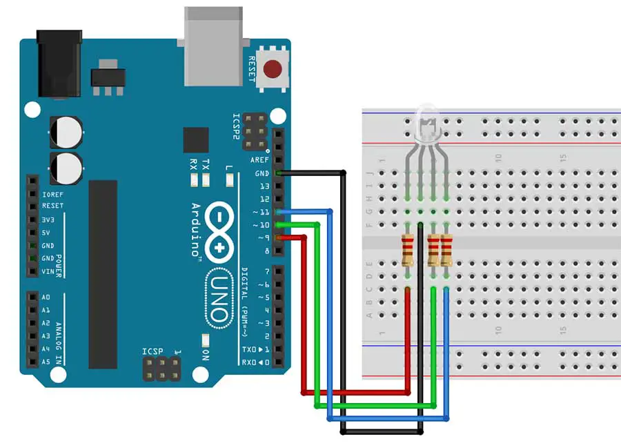
For a common cathode RGB LED:
- Connect the red anode to digital pin 9.
- Connect the green anode to digital pin 10.
- Connect the blue anode to digital pin 11.
- Connect the common cathode to the GND pin on Arduino.
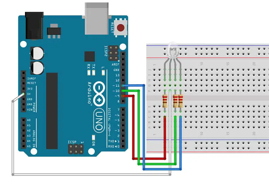
For a common anode RGB LED:
- Connect the red anode to digital pin 9 through a 220-ohm resistor.
- Connect the green anode to digital pin 10 through a 220-ohm resistor.
- Connect the blue anode to digital pin 11 through a 220-ohm resistor.
- Connect the common anode to the 5V pin on Arduino
Step 3: Uploading the Arduino Code
Now, let's write the Arduino code to control the RGB LED. For this project, we will simply cycle through red, green, blue, and purple colors with a 1-second delay between each color.
Open the Arduino IDE on your computer and choose either of the following codes depending on the type of RGB LED you have.
If you are using a common cathode, write this code:
//This sketch is for the common cathode type of RGB LED
//for common cathode, 255 means full color display and 0 means color is not displayed
int r_led= 9;
int g_led = 10;
int b_led = 11;
void setup() {
pinMode(r_led, OUTPUT);
pinMode(g_led, OUTPUT);
pinMode(b_led, OUTPUT);
}
void loop() {
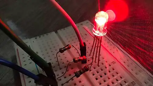
// Red color (full red, no green, no blue)
analogWrite(r_led, 255);
analogWrite(g_led, 0);
analogWrite(b_led, 0);
delay(1000);
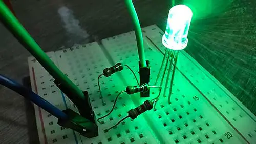
// Green color (no red, full green, no blue)
analogWrite(r_led, 0);
analogWrite(g_led, 255);
analogWrite(b_led, 0);
delay(1000);
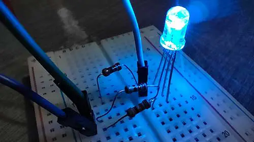
// Blue color (no red, no green, full blue)
analogWrite(r_led, 0);
analogWrite(g_led, 0);
analogWrite(b_led, 255);
delay(1000);
// Purple color (full red, no green, full blue)
analogWrite(r_led, 255);
analogWrite(g_led, 0);
analogWrite(b_led, 255);
delay(1000);
}
Here's how it works:
In order to produce red, we simply illuminate the red LED at 100% intensity by giving it a value of 255, and turning off the green and blue led by giving it a value of 0 in the analogWrite() function, as shown in this code snippet:
    // Red color (full red, no green, no blue)
    analogWrite(r_led, 255);
    analogWrite(g_led, 0);
    analogWrite(b_led, 0);
And in order to produce more colors, such as purple, we simply illuminate the red LED and blue LED at 100% intensity, and turn off the green LED. We know that if we mix equal amounts of red and blue, we get purple. This is shown in this code snippet:
    // Purple color (full red, no green, full blue)
    analogWrite(r_led, 255);
    analogWrite(g_led, 0);
    analogWrite(b_led, 255);
If you are using a common anode, write this code:
  //This sketch is for the common anode type of RGB LED
  //for common anode, 0 means full color display and 255 means color is not displayed

  int r_led= 9;
  int g_led = 10;
  int b_led = 11;

  void setup() {
    pinMode(r_led, OUTPUT);
    pinMode(g_led, OUTPUT);
    pinMode(b_led, OUTPUT);
  }

  void loop() {

    // Red color (full red, no green, no blue)
    analogWrite(r_led, 0);
    analogWrite(g_led, 255);
    analogWrite(b_led, 255);

    delay(1000);

     // Green color (no red, full green, no blue)
    analogWrite(r_led, 255);
    analogWrite(g_led, 0);
    analogWrite(b_led, 255);

    delay(1000);

    // Blue color (no red, no green, full blue)
    analogWrite(r_led, 255);
    analogWrite(g_led, 255);
    analogWrite(b_led, 0);

    delay(1000);

    // Purple color (full red, no green, full blue)
    analogWrite(r_led, 0);
    analogWrite(g_led, 255);
    analogWrite(b_led, 0);

    delay(1000);

    }
Here's how it works:
The common anode RGB LED works the opposite way with the common cathode. For example, in order to produce red, we illuminate the red LED at 100% intensity by giving it a value of 0 (instead of 255), and turning off the green and blue LED by giving it a value of 255 (instead of 0) in the analogWrite() function, as shown in this code snippet:
    // Red color (full red, no green, no blue)
    analogWrite(r_led, 0);
    analogWrite(g_led, 255);
    analogWrite(b_led, 255);
In order to produce purple, we illuminate the red LED and blue LED at 100% intensity by giving it a value of 0 (instead of 255) and turn off the green LED by giving it a value of 255. Take a look at this code snippet:
    // Purple color (full red, no green, full blue)
    analogWrite(r_led, 0);
    analogWrite(g_led, 255);
    analogWrite(b_led, 0);
Step 4: Uploading the Code and Testing
Connect your Arduino board to your computer using the USB cable. Make sure you have selected the correct board and port in the Arduino IDE. Then, click on the "Upload" button to upload the code to your Arduino board.
Once the code is uploaded, you should see the RGB LED changing colors according to the code. It will cycle through red, green, blue, and purple colors with a 1-second delay between each color.
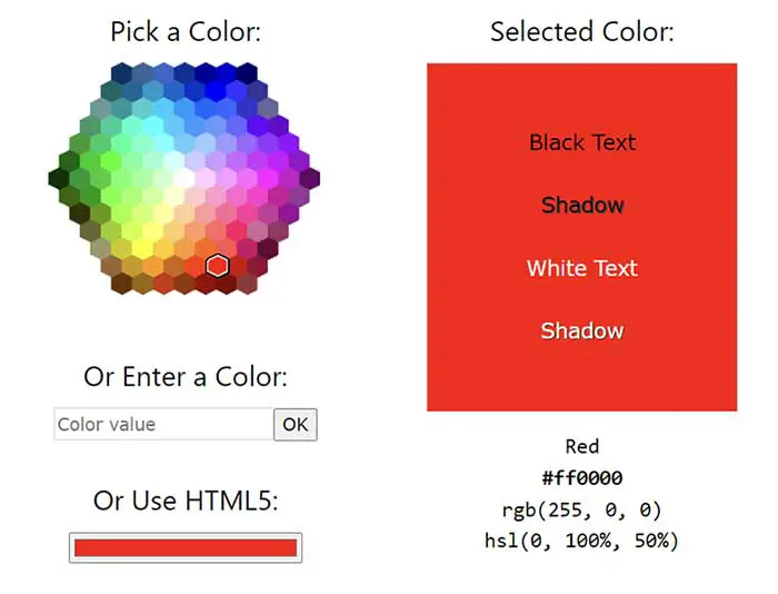
More about Color Mixing
To mix RGB colors, you may use this online resource.
Remember to consult the datasheet for your specific RGB LED, as there may be slight variations in how they operate. Additionally, always respect the voltage and current specifications to prevent damage to your components.
Watch the YouTube video of this project:
PROJECT 2: RGB LED Using a Custom Function
Simplifying the Code
We can shorten our sketch by writing a custom function.
In Arduino programming, a custom function is a user-defined block of code that performs a specific task. It allows you to break down your program into smaller, more manageable pieces, making your code more organized, modular, and easier to understand.
Here are the key aspects of custom functions in Arduino:
-
Definition:
- A custom function is created by the user and given a unique name. It can take input parameters (arguments) and may return a value.
-
Syntax:
- The basic syntax for defining a function in Arduino is as follows:
return_type function_name(parameter1_type parameter1_name, parameter2_type parameter2_name, ...) { // Function body (code to perform the task) }return_type: The data type of the value the function will return (if any). Usevoidif the function does not return a value.function_name: A unique identifier for the function.parameter1_type,parameter2_type, etc.: Data types of any input parameters the function requires.parameter1_name,parameter2_name, etc.: Names of the input parameters.
- The basic syntax for defining a function in Arduino is as follows:
-
Calling a Function:
- To use a function, you "call" it by its name, followed by any required arguments in parentheses.
function_name(argument1, argument2, ...);
- To use a function, you "call" it by its name, followed by any required arguments in parentheses.
-
Reusability:
- Once defined, you can call a function as many times as needed from different parts of your program. This promotes code reusability.
Custom functions are a fundamental aspect of structured programming and are crucial for writing clear, modular, and efficient code.
Here's the shortened code for the common cathode, using a custom function:
  //common cathode using a custom function

  int r_led= 3;
  int g_led = 5;
  int b_led = 6;

  void setup() {
    pinMode(r_led, OUTPUT);
    pinMode(g_led, OUTPUT);
    pinMode(b_led, OUTPUT);
  }

  void loop() {
    ledColor(255, 0, 0); // red
    delay(1000);

    ledColor(0, 255, 0); // green
    delay(1000);

    ledColor(0, 0, 255); // blue
    delay(1000);

    ledColor(128, 0, 128); // purple
    delay(1000);


  }

  //create a custom function with a name: ledColor
  void ledColor(int rValue, int gValue, int bValue) {
    analogWrite(r_led, rValue);
    analogWrite(g_led, gValue);
    analogWrite(b_led, bValue);
  }
In this sketch, we created our very own custom function and we gave it a name. The name of the function in this case is ledColor. You may choose to have your own function name.
  //create a custom function with a name: ledColor
  void ledColor(int rValue, int gValue, int bValue) {
    analogWrite(r_led, rValue);
    analogWrite(g_led, gValue);
    analogWrite(b_led, bValue);
  }
This custom will then be "called" inside our void loop() function. The loop() now becomes clear and more efficient because we only need to write only one line of code instead of three.
ledColor(255, 0, 0); // red
Here's the shortened code for the common anode:
  //common anode using a custom function

  int r_led= 3;
  int g_led = 5;
  int b_led = 6;

  void setup() {
    pinMode(r_led, OUTPUT);
    pinMode(g_led, OUTPUT);
    pinMode(b_led, OUTPUT);
  }

  void loop() {
    ledColor(255, 0, 0); // red
    delay(1000);

    ledColor(0, 255, 0); // green
    delay(1000);

    ledColor(0, 0, 255); // blue
    delay(1000);

    ledColor(128, 0, 128); // purple
    delay(1000);


  }

  //create a custom function with a name: ledColor
  void ledColor(int rValue, int gValue, int bValue) {
    analogWrite(r_led, 255-rValue);
    analogWrite(g_led, 255-gValue);
    analogWrite(b_led, 255-bValue);
  }
By using this custom function for the common anode, we no longer need to worry about its opposite values. We just supply the RGB codes we get from online color pickers, and let the custom function do the computation for us by computing its opposite value. For example, if the value is 0, our custom function will make it 255, as shown in this code:
  //create a custom function with a name: ledColor
  void ledColor(int rValue, int gValue, int bValue) {
    analogWrite(r_led, 255-rValue);
    analogWrite(g_led, 255-gValue);
    analogWrite(b_led, 255-bValue);
  }
Bonus RGB LED Code!
If you want to have a smooth transition from one color to another, you may check out this code from another article on this site:
Project 2: Fading RGB LED Effect: Smooth Color Transition
Conclusion
Congratulations! You have successfully learned how to control an RGB LED with Arduino. By manipulating the values for red, green, and blue, you can create a wide range of colors and effects. Experiment with different combinations and timings to achieve the desired visual effects. Have fun exploring the world of RGB LEDs and Arduino!


