Unlock the full potential of your Arduino projects by integrating a DS1302 Real Time Clock (RTC) module. This friendly and comprehensive guide will equip you with everything you need to seamlessly interface the DS1302 RTC module with an Arduino, ensuring accurate timekeeping and displaying it on a bright and easy-to-read LCD screen. From understanding the hardware components to mastering the code, this tutorial is designed to be a valuable resource for beginners and seasoned hobbyists alike.
What is the DS1302 Real Time Clock Module?
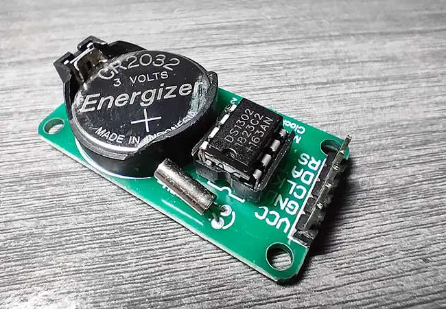
The DS1302 RTC module is a low-power clock module that keeps accurate time and date. It can track seconds, minutes, hours, day, date, month, and year, with leap year compensation valid up to 2100. This module is particularly useful in projects where you need to keep track of time, such as data loggers, timers, and alarms.
Why Use the DS1302 RTC Module with Arduino?
The DS1302 module is reliable and easy to interface with Arduino, making it ideal for beginners. Its low power consumption means it can run on a small battery for years, maintaining accurate time even when the main power is off.
Practical Application: Creating a Digital Clock with Arduino
Imagine having a sleek digital clock that displays the current time and date on an LCD screen, which you built yourself! This project will teach you how to use the DS1302 RTC module and an I2C LCD to create a digital clock. It’s a perfect project for beginners to learn about timekeeping and LCD displays while creating something functional and visually appealing.
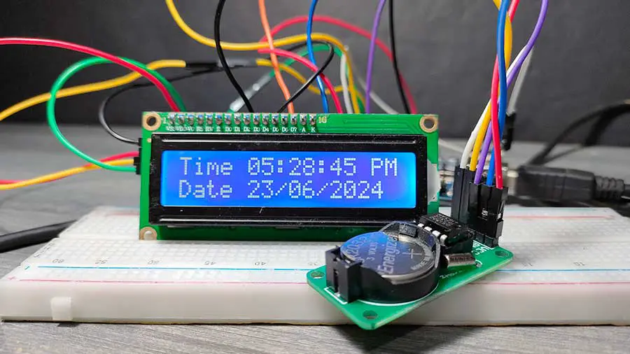
Here is my Arduino clock running:
Components Needed
- Arduino UNO
- DS1302 RTC Module
- 16x2 I2C LCD Display
- Breadboard and Jumper Wires
- 3V Battery (for the RTC module)
Step-by-Step Guide
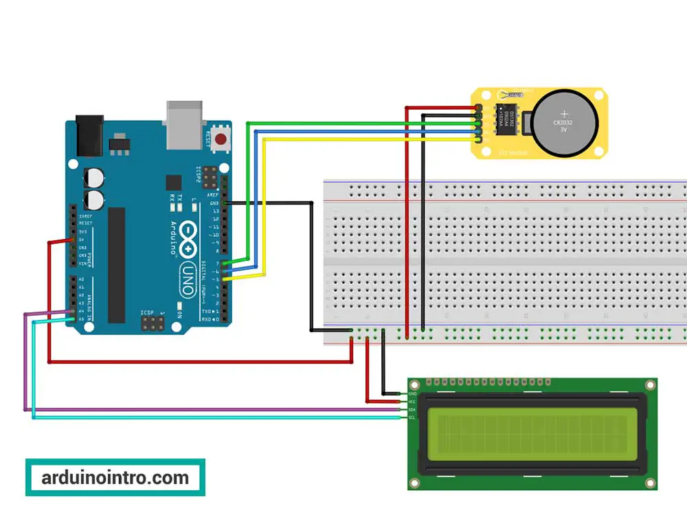
Step 1: Setting Up the Hardware
-
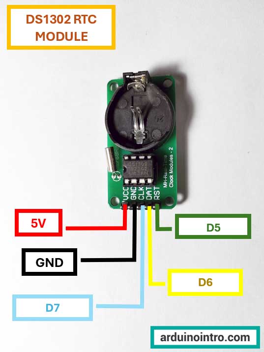
Connect the DS1302 RTC Module to Arduino:
- VCC to 5V on Arduino
- GND to GND on Arduino
- CLK to Pin 7 on Arduino
- DAT to Pin 6 on Arduino
- RST to Pin 5 on Arduino
-
Connect the I2C LCD Display to Arduino:
- GND to GND on Arduino
- VCC to 5V on Arduino
- SDA to A4 on Arduino
- SCL to A5 on Arduino
Step 2: Installing the Required Libraries
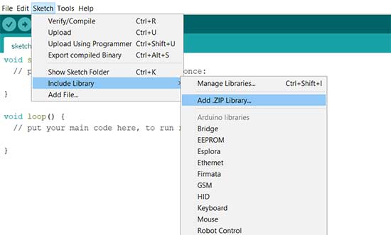
Before we can start coding, you need to install the necessary libraries. You can download the libraries needed for this project at the end of this article. After downloading the zip files, open the Arduino IDE and navigate to Sketch > Include Library > Add .ZIP Library. Browse to where you downloaded the zip files and click OK to install these libraries.
How to Install a Library in Arduino IDE
|
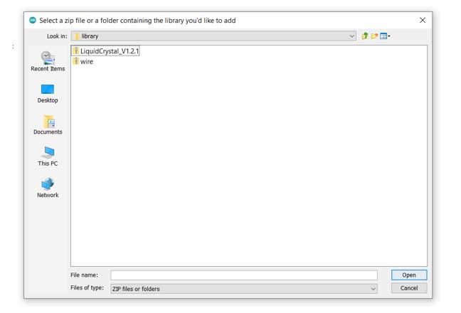
Here is an example of how to install a library. In this example, we will install the LiquidCrystal_V1.2.1 library.
Step 1. First, download the library you wish to install. It should be in a zip file. Step 2. Open your Arduino IDE and from the menu bar, go to Sketch->Include Library->Add.ZIP Library..
Step 3. Browse to where you saved the zip file then click Open. In this example, we select the LiquidCrystal_V1.2.1 zip file.
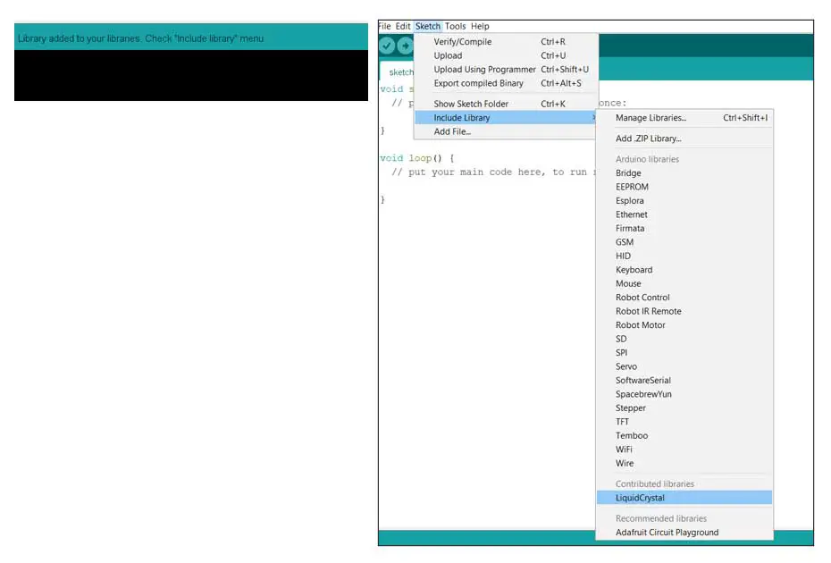
After clicking Open, the library is now installed.
Step 4. Repeat the same process if you wish to include more libraries.
|
Step 3: Writing the Arduino Code
Here is the complete code to get the DS1302 RTC module working with your Arduino and display the time on an I2C LCD.
#include <Wire.h>
#include <DS1302.h>
#include <LiquidCrystal_I2C.h>

// Initialize the DS1302
const int CE_PIN = 5;
const int IO_PIN = 6;
const int SCLK_PIN = 7;

DS1302 rtc(CE_PIN, IO_PIN, SCLK_PIN);

// Initialize the LCD
LiquidCrystal_I2C lcd(0x27, 2, 1, 0, 4, 5, 6, 7, 3, POSITIVE);

void setup() {
  // Initialize the LCD
  lcd.begin(16, 2);
  rtc.halt(false);
  rtc.writeProtect(false);

  // Set the initial time

  // Make a new time object to set the date and time. use 24-hour format
  // Example: Sunday, June 23, 2024 at 05:24:50 PM.
  // uncomment next line to set a new date time
  // Time t(2024, 6, 23, 17, 24, 50, Time::kSunday);

  // Set the time and date on the chip.
  // uncomment next line to set a new date time
  // rtc.time(t);

  //after uncommenting these lines, upload your code.
  //then comment the lines again and upload again.
}

void loop() {
  // Get the current time and date from the RTC
  Time t = rtc.time();

  // Determine AM or PM and convert 24-hour format to 12-hour format
  String period = "AM";
  int hour = t.hr;
  if (t.hr >= 12) {
    period = "PM";
    if (t.hr > 12) {
      hour = t.hr - 12;
    }
  } else {
    if (t.hr == 0) {
      hour = 12;
    }
  }

  // Display the time
  lcd.setCursor(0, 0);
  lcd.print("Time ");
  if (hour < 10) lcd.print("0");
  lcd.print(hour);
  lcd.print(":");
  if (t.min < 10) lcd.print("0");
  lcd.print(t.min);
  lcd.print(":");
  if (t.sec < 10) lcd.print("0");
  lcd.print(t.sec);
  lcd.print(" ");
  lcd.print(period);

  // Display the date
  lcd.setCursor(0, 1);
  lcd.print("Date ");
  if (t.date < 10) lcd.print("0");
  lcd.print(t.date);
  lcd.print("/");
  if (t.mon < 10) lcd.print("0");
  lcd.print(t.mon);
  lcd.print("/");
  lcd.print(t.yr);

  delay(1000); // Update every second
}
Step 4: Uploading the Code
Connect your Arduino to your computer and upload the code using the Arduino IDE. Once the upload is complete, the LCD should start displaying the current time and date.
Understanding the Code
Let's go through the code step-by-step to understand how it works.
Include Necessary Libraries
#include <Wire.h>
#include <DS1302.h>
#include <LiquidCrystal_I2C.h>
These lines include the necessary libraries for the project:
Wire.h: Allows communication with I2C devices.DS1302.h: Manages the DS1302 Real Time Clock module.LiquidCrystal_I2C.h: Manages the I2C LCD display.
Initialize the DS1302 RTC Module
const int CE_PIN = 5;
const int IO_PIN = 6;
const int SCLK_PIN = 7;

DS1302 rtc(CE_PIN, IO_PIN, SCLK_PIN);
These lines define the pin connections for the DS1302 RTC module and create an rtc object using those pins:
CE_PIN: Chip Enable pin connected to Arduino pin 5.IO_PIN: Input/Output pin connected to Arduino pin 6.SCLK_PIN: Serial Clock pin connected to Arduino pin 7.
Initialize the LCD
LiquidCrystal_I2C lcd(0x27, 2, 1, 0, 4, 5, 6, 7, 3, POSITIVE);
Creates an lcd object for the I2C LCD with the specified parameters:
0x27: The I2C address of the LCD.- The remaining numbers are the pin mappings of the LCD (specific to the library being used).
Setup Function
void setup() {
  lcd.begin(16, 2);
  rtc.halt(false);
  rtc.writeProtect(false);

  // Set the initial time
  // Make a new time object to set the date and time. use 24-hour format
  // Example: Sunday, June 23, 2024 at 05:24:50 PM.
  // uncomment next line to set a new date time
  // Time t(2024, 6, 23, 17, 24, 50, Time::kSunday);

  // Set the time and date on the chip.
  // uncomment next line to set a new date time
  // rtc.time(t);

  // after uncommenting these lines, upload your code.
  // then comment the lines again and upload again.
}
-
lcd.begin(16, 2);: Initializes the LCD with 16 columns and 2 rows. -
rtc.halt(false);: Ensures the RTC is running (not halted). -
rtc.writeProtect(false);: Disables write protection to allow changes to the RTC time and date. -
Comments guide users on how to set the initial time:
// Time t(2024, 6, 23, 17, 24, 50, Time::kSunday);: Example of setting a new time object. Uncomment and modify to set the desired initial time.// rtc.time(t);: Sets the time on the RTC. Uncomment to set the new time initially.- After setting the initial time, users should upload the code, then comment the lines again and re-upload to avoid resetting the time each time the Arduino restarts.
Loop Function
The loop function runs repeatedly, updating the time and date display every second:
Get the Current Time:
Time t = rtc.time();
Retrieves the current time and date from the RTC module.
Convert to 12-Hour Format and Determine AM/PM:
String period = "AM";
int hour = t.hr;
if (t.hr >= 12) {
  period = "PM";
  if (t.hr > 12) {
    hour = t.hr - 12;
  }
} else {
  if (t.hr == 0) {
    hour = 12;
  }
}
- Initializes the
periodstring to "AM". - If the hour (
t.hr) is 12 or more, setsperiodto "PM". - Converts the 24-hour format to 12-hour format by subtracting 12 if necessary.
- Adjusts midnight (0:00) to 12 AM.
Display the Time:
lcd.setCursor(0, 0);
lcd.print("Time ");
if (hour < 10) lcd.print("0");
lcd.print(hour);
lcd.print(":");
if (t.min < 10) lcd.print("0");
lcd.print(t.min);
lcd.print(":");
if (t.sec < 10) lcd.print("0");
lcd.print(t.sec);
lcd.print(" ");
lcd.print(period);
- Sets the cursor to the beginning of the first row.
- Prints the current time in 12-hour format with leading zeros for single-digit hours, minutes, and seconds.
- Prints the AM/PM period.
Display the Date:
lcd.setCursor(0, 1);
lcd.print("Date ");
if (t.date < 10) lcd.print("0");
lcd.print(t.date);
lcd.print("/");
if (t.mon < 10) lcd.print("0");
lcd.print(t.mon);
lcd.print("/");
lcd.print(t.yr);
- Sets the cursor to the beginning of the second row.
- Prints the current date with leading zeros for single-digit days and months.
Update Every Second:
delay(1000);
Pauses the program for 1000 milliseconds (1 second) before updating the display again.
This code continuously updates the time and date on the LCD, displaying the time in 12-hour format with an AM/PM indicator.
Want to learn more about the DS1302 module in video format? Watch this video:
Troubleshooting Tips
- Incorrect Time/Date: If the time or date is incorrect, you may need to uncomment the lines in the setup function that set the initial time and date, upload the code once, and then comment them out again.
- LCD Not Displaying Correctly: Double-check all the connections between the LCD and the Arduino. Ensure the I2C address is correct (0x27 is common but can vary). You may also need to check or even replace your jumper wires.
Conclusion
By following this guide, you should now have a functional digital clock using the DS1302 RTC module and an Arduino with an I2C LCD. This project is a great starting point for anyone new to Arduino, as it covers fundamental concepts such as interfacing with hardware, using libraries, and displaying data. As you become more comfortable with these components, you can expand your project by adding alarms, temperature sensors, or even connecting it to the internet.
Downloads:


Thanks!