Breadboards are one of the most fundamental pieces when learning how to build circuits. It is a solderless construction base used for developing an electronic circuit and wiring for projects with microcontroller boards like Arduino. Breadboards are made for doing quick experiments. They are not known for keeping circuits together for a long time. The connections are not permanent, so it is easy to remove a component if you make a mistake, or just start over and do a new project.
This makes breadboards great for beginners who are new to electronics. Because it’s not for permanent circuit connections, you can freely pull out the electronic components from the holes to reconnect or remove the circuit without the need of soldering and assembling, and also importantly it allows the components to be repeatedly used, which makes it perfect for prototyping, debugging and learning electronic circuits
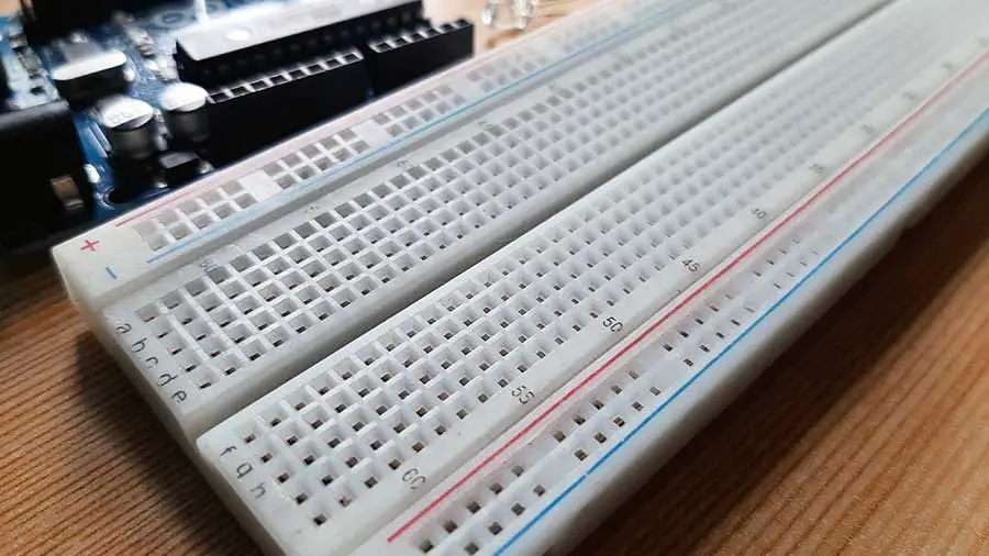
The first thing you should notice about the breadboard is all of the holes. These are broken up into 2 sets of columns and a set of rows (the rows are divided in the middle called a groove). The columns on the edges are connected from top to bottom inside of the breadboard to make it easy to supply power and ground. Inside the breadboard, the holes in each row are connected up to the groove in the middle of the board.
Breadboard Components
To help you get started with connecting things with a breadboard, you need to know its components and features.
Basically, there are three functional areas on a breadboard, the power rails near the long sides, the terminal strips (in some breadboards, these are the holes from rows a to j), and the middle groove. And remember that the inside of the breadboard (under the holes) is made up of sets of five metal clips.
The power rails are typically used to supply electrical power to your circuit when you connect them to a battery pack or other external power supply. Note that only holes in the same strip forming a row are electrically connected to each other. It is important to be aware that the power rails on either side are not connected, so if you want the same power source on both sides, you will need to connect the two sides with some jumper wires. Keep in mind that the markings are there just as a reference. There is no rule that says you have to plug power into the '+' rail and ground into the '-' rail, though it is a good practice to keep everything in order.
Terminal strips are the main work area separated by the middle groove into two parts (rails a-e and rails f-j). They are mainly used for electrical components. You may have noticed that many breadboards have numbers and letters marked on various rows and columns. These don't serve any purpose other than to help guide you when building your circuit. Circuits can get complicated quickly, and all it takes is one misplaced leg of a component to make the entire circuit malfunction or not work at all. If you know the row number of the connection you are trying to make, it makes it much simpler to plug a wire into that number. Each set of five holes forming a half-column is electrically connected, meaning that hole a1 is electrically connected to holes b1, c1, d1 and e1, but not connected to hole a2, because that hole is in a different column, with a separate set of metal clips. Also holes a1- e1 are not connected to holes f1, g1, h1, i1, and j1, because they are electrically separated by the middle groove.
Here we have a breadboard where the adhesive backing has been removed.
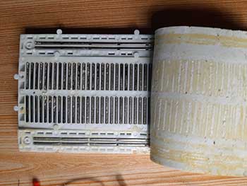
You can see lots of horizontal rows of metal strips on the bottom of the breadboard. The tops of the metal rows have little clips that hide under the plastic holes. These clips allow you to stick a wire or the leg of a component into the exposed holes on a breadboard, which then hold it in place. Once inserted that component will be electrically connected to anything else placed in that row. This is because the metal rows are conductive and allow current to flow from any point in that strip.
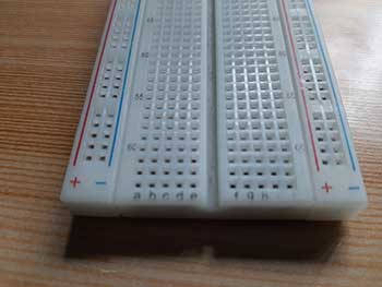
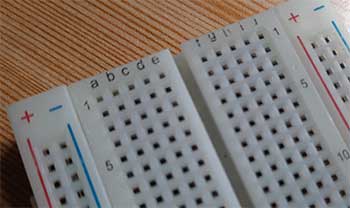
Note that exact configurations might vary from breadboard to breadboard. For example, some breadboards have labels printed in "landscape" orientation instead of "portrait" orientation. Most "mini" breadboards do not have power rails or labels printed on them at all.
Making connections on the Breadboard
In connecting components with the breadboard, you may need to use jumper wires. Jumper wires are wires that have stiff ends that are easy to push into the breadboard holes.
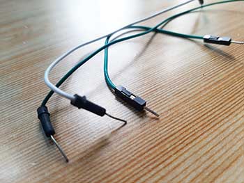
You can also buy spools of solid-core hookup wire and a pair of wire strippers and cut your own jumper wires. This is the best long-term option if you plan on doing lots of electronics projects because you can cut wires to the exact length you need, and pick which colors you want. It is also much more cost-effective per length of wire. You also need to use the right wire gauge, which is a way of measuring wire diameter. 22 AWG (American Wire Gauge) is the most common gauge used for breadboards.
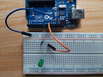
Here’s a simple LED circuit we can make on a breadboard.
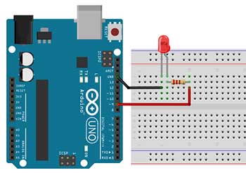
You may see a lot of breadboard diagrams like this on the internet. Breadboard diagrams make it easy for beginners to follow instructions to build a circuit because they are designed to look like the "real thing." Just remember that you don’t have to match the breadboard diagram exactly. You just have to understand how things are connected on a breadboard.


