Having one sensor in your Arduino project is already an achievement. But why stop at one? With the Arduino board, it is possible to add as many sensors as you can. In this article, I will show you how to use an infrared sensor and a touch sensor to control an LED. The key to successfully combining more than one sensor is knowing how to check the current states of all connected sensors. To help you determine whether all your sensors are triggered, you have to know the various Relational and Conditional Operators in Arduino.
Relational Operators
Relational operators indicate the relationship among two operands. Here is a summary of all relational operators in Arduino:
|
OPERATOR |
EXAMPLE |
MEANING |
|
> |
val > 1 |
val is greater than 1 |
|
>= |
val >= 1 |
val is greater than or equal to 1 |
|
< |
val < 1 |
val is less than 1 |
|
<= |
val <= 1 |
val is less than or equal to 1 |
|
== |
val == 1 |
val is equal 1 |
|
!= |
val != 1 |
val is not equal to 1 |
Relational operators are commonly used to create a condition for the if statement. For example:
if (val < 1 ) {

                digitalWrite(ledpin,HIGH);

}
The condition (val < 1) will result in either a TRUE or FALSE, depending on the current value of the val variable.
Conditional/Logical Operators
Much like Relational operators, the result of using Conditional or Logical Operators is either a TRUE or a FALSE.
These are the Conditional Operators in Arduino:
|
OPERATOR |
MEANING |
|
! |
NOT |
|
|| |
OR |
|
&& |
AND |
Truth Tables
Truth tables will help us demonstrate the result of a logical expression. Below are the truth tables that you will need for evaluating logical operations.
The NOT (!) operator negates the value of the operand.
|
|
OPERAND |
RESULT |
|
! |
true |
false |
|
! |
false |
true |
The OR (||) operator returns true if at least one of its operands is true.
|
OPERAND 1 |
|
OPERAND 2 |
RESULT |
|
true |
|| |
true |
true |
|
true |
|| |
false |
true |
|
false |
|| |
true |
true |
|
false |
|| |
false |
false |
The AND (&&) operator returns true only when both operands are true. Otherwise, it will return false.
|
OPERAND 1 |
|
OPERAND 2 |
RESULT |
|
true |
&& |
true |
true |
|
true |
&& |
false |
false |
|
false |
&& |
true |
false |
|
false |
&& |
false |
false |
PROJECT 1: 2 Sensors 1 LED
Make the 2-sensor Project
Now that we know the relational and conditional operators, let’s try using them in an Arduino project.
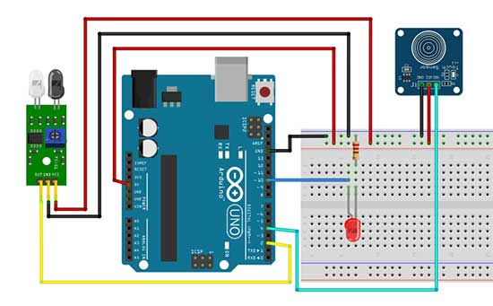
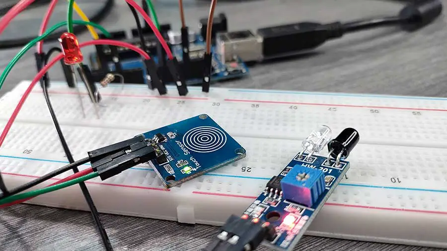
This project uses the HW-201 infrared (IR) obstacle sensor module and a TTP223B capacitive touch sensor module. However, you can always use whatever sensor you have available. The objective of this project is to turn on the LED if BOTH of the sensors are triggered.
Let’s take a look at the breadboard circuit.

Connecting the components is pretty straightforward. Just connect them to their appropriate pins. However, there’s just one minor problem. Both the infrared and the touch sensor use the 5V pin of the Arduino. Unfortunately, there is only one 5V pin available. The solution is to connect one jumper wire from the 5V pin to one of the power rails in the breadboard. As a result, the entire strip will supply the needed 5V to all the sensors.
Now, let’s go to the sketch.
  //Switch an LED using a touch sensor and ir sensor

  int touchsensor = 4;
  int ir = 2;
  int PinLed = 10;


  void setup()
  {
    pinMode(touchsensor, INPUT);
    pinMode(ir, INPUT);
    pinMode(PinLed, OUTPUT);

  }

  void loop()
  {
    //both sensors are triggered
    //You may need to check the serial monitor for the 1 and 0 values
    //The 1 and 0 may depend on the type of sensor
    //feel free to change 1 to 0 or vice-versa depending on your project
    if(digitalRead(touchsensor) == 1 && digitalRead(ir) == 1)
    {
      digitalWrite(PinLed, HIGH);
    }
    else
    {
      digitalWrite(PinLed, LOW);
    }
  }
Again, our objective is to turn on the LED if both sensors are triggered. Let’s go immediately to the loop function. The loop function only contains the if-else statement. The important part here is the conditional statement. Basically, what we are trying to tell Arduino is: if both sensors are triggered, then, turn on the LED. Otherwise, turn it off. That’s it. This is how it is converted to actual code:
if(digitalRead(touchsensor) == 1 && digitalRead(ir) == 1)Operand 1 is: digitalRead(touchsensor) == 1
Operand 2 is: digitalRead(ir) == 1
The operator is: AND (&&)
Based on our Truth tables, both operands must be true in order for the entire condition to be true. And once it evaluates to true, the LED will be turned on.
Just a quick note, this part of the code assumes that when the sensors are triggered, the digital signal you’ll be getting is 1. However, this is not always the case. Some sensors may give a 0 when they are triggered. To be sure, you may need to check the serial monitor for the 1 and 0 values. In this case, you have to include the Serial.begin() and Serial.println() functions. Or, you can do a simple trial and error by changing 1 to 0 and vice-versa.
PROJECT 2: 2 Sensors 2 LEDs
Make it 2 LEDs
The previous project is already fine, but we can still improve it. Let's try to turn on and turn off 2 LEDs based on the following conditions:
|
TOUCH SENSOR |
IR SENSOR |
LED 1 |
LED2 |
|
Touch detected |
Object detected |
ON |
ON |
|
Touch detected |
NO Object detected |
OFF |
ON |
|
NO touch detected |
Object detected |
ON |
OFF |
|
NO touch detected |
NO Object detected |
OFF |
OFF |
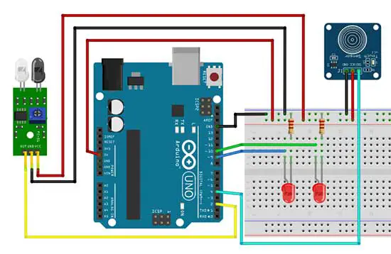
Here is the breadboard circuit.

We have simply added one LED to our previous circuit.
This will be our Arduino sketch:
//Control 2 LEDs using a touch sensor and ir sensor

  int touchsensor = 4;
  int ir = 2;
  int led9=9, led10 = 10;


  void setup()
  {
    pinMode(touchsensor, INPUT);
    pinMode(ir, INPUT);
    pinMode(led10, OUTPUT);
    pinMode(led9, OUTPUT);

  }

  void loop()
  {
    //both sensors are triggered
    //You may need to check the serial monitor for the 1 and 0 values
    //The 1 and 0 may depend on the type of sensor
    //feel free to change 1 to 0 or vice-versa depending on your project

    if(digitalRead(touchsensor) == 1 && digitalRead(ir) == 1)
    {
      digitalWrite(led10, HIGH);
      digitalWrite(led9, HIGH);
    }
    else if (digitalRead(touchsensor) == 1 && digitalRead(ir) == 0)
    {
      digitalWrite(led10, LOW);
      digitalWrite(led9, HIGH);
    }
    else if (digitalRead(touchsensor) == 0 && digitalRead(ir) == 1)
    {
      digitalWrite(led10, HIGH);
      digitalWrite(led9, LOW);
    }
    else if (digitalRead(touchsensor) == 0 && digitalRead(ir) == 0)
    {
      digitalWrite(led10, LOW);
      digitalWrite(led9, LOW);
    }
  }
The heart of this sketch is the if-else if statement. This statement is used if we are going to evaluate more than 1 condition. In this project, we have four conditions to be evaluated, based on the current status of the sensors.
This is the syntax of the if-else if statement:
if (condition 1){
   <statement/s>;
}
else if (condition 2){
   <statement/s>;
else if (condition 3){
   <statement/s>;
}
.
.
.
else if (condition n){
   <statement/s>;
}
You can have as many conditions as needed for the if-else if statement.
What we did here is to add one else if statement for each of the four conditions. Take note that only one block of statements will be executed and the rest will be ignored. For example, if the first condition is true, then only the block inside that if condition will be executed. After the code block is executed, Arduino will skip the rest of the else if statement. If the first condition is false, then it proceeds to the next condition until it encounters a condition that evaluates to true.


