In the first stage of this project, we will learn how to move the servo motor smoothly using a for-loop. After that, we will attach an infrared sensor to the servo horn so that we can detect objects in a sweeping motion from left to right. We will include an LED to indicate that our radar has detected an object.
PROJECT 1: Smooth Servo Motion
In this project, we will move the servo smoothly from left to right just like a radar’s scanning motion.
Materials
- 1 Servo Motor
- 1 Arduino Microcontroller
Breadboard
Arduino Sketch
#include <Servo.h>
Servo myServo;

int servoPin = 3;


void setup()
{
  myServo.attach(servoPin);
}

void loop()
{
  for (int i=20;i<=160;i=i+1)
  {
    myServo.write(i);
    delay(20);
  }

  for (int i=160;i>=20;i=i-1)
  {
    myServo.write(i);
    delay(20);
  }

}
Explanation
#include <Servo.h>The first part of this code is to set up our servo motor. The first line lets us link to the servo library so we can access the pre-written servo codes.
Servo myServo;Next, we create an object from the Servo class. The name of our object in this project is myServo.
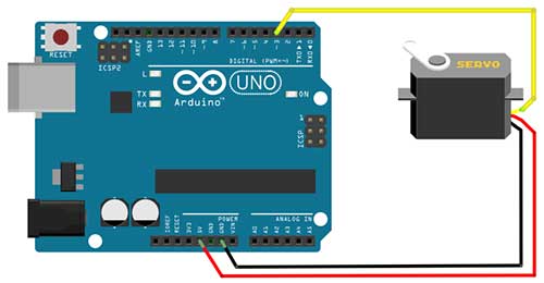
int servoPin = 3;The servoPin variable is where our servo is connected to the Arduino board. In this case, it is connected to pin 3.
myServo.attach(servoPin);This line attaches our servo object to a pin.
The servo motor we are using is the Tower Pro SG90 micro servo and it has a range from 20-160 degrees. For a smooth sweeping motion, we will use the for-loop. For a complete explanation of the for-loop, you may want to read this article: Become a Master of the Fade In Fade Out Effect (Arduino Style)
  for (int i=20;i<=160;i=i+1)
  {
    myServo.write(i);
    delay(20);
  }
Basically, the statements found inside the for loop will be repeatedly executed until such time that a certain is met. Once this condition is met, the loop will end.
for (int i=20; i<=160; i=i+1)
The first part is to declare a variable that holds our initial angle. The variable we used here is i with a value of 20 which corresponds to our minimum angle.
for (int i=20; i<=160; i=i+1)
This part here is the condition. As long as this condition is TRUE, the loop will continue to run. If this becomes FALSE, then the loop will stop and Arduino will proceed to the next statement. This condition will be checked every time the first statement inside the loop is to be executed again.
for (int i=20; i<=160; i=i+1)
The last part lets us change the current value of our variable. This is important because this will affect our condition part. If the variable’s value will not change, then we will be stuck in a never-ending loop. In this example, we just add 1 to the current value of the i variable every time the loop repeats. Eventually, the value of i will become 161, and this will make the condition false, hence, the loop stops.
Now inside the loop, we only have two statements.
    myServo.write(i);
    delay(20);
This statement moves the servo to an angle which is the current value of i. A delay is added to give time for the servo shaft to travel to that angle. Since the difference from the previous angle is just one, we can supply it with a very short delay of 20 milliseconds. Actually, you can experiment with the delay and see which works best for you.
  for (int i=160;i>=20;i=i-1)
  {
    myServo.write(i);
    delay(20);
  }
The next statement is another for loop that is very similar to the first one. This time, our starting angle is 160. And then every time the loop repeats, the current value of i will be subtracted by 1, until such time the condition becomes FALSE.
PROJECT 2: Radar System
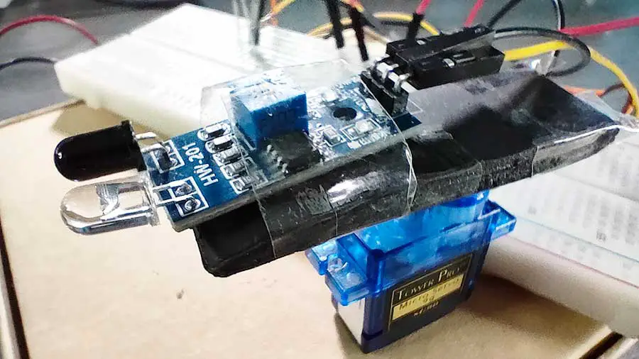
In this next stage, we are now ready to add our object detection module. I am using the HW-201 IR Sensor but you may use any sensor you like. The IR sensor will be attached to the servo horn so that it moves together with the servo. In a sweeping motion, the sensor will be scanning for objects in front of it. This can be a useful guidance system for a mobile robot.
Materials
- 1 IR sensor
- 1 Servo Motor
- 1 Arduino Microcontroller
- 1 LED
- 1 220-ohm Resistor
Breadboard

Arduino Sketch
#include <Servo.h>
Servo myServo;

int servoPin = 3;
int ir=5;
int led =2;


void setup()
{
  myServo.attach(servoPin);
  pinMode(ir,INPUT);
  pinMode(led,OUTPUT);
}

void loop()
{
  for (int i=20;i<=160;i=i+1)
  {
    myServo.write(i);
    delay(20);

    //check if an object is detected
    //in my case a 0 means an object is detected.
    //You may change this to 1 if necessary
    if (digitalRead(ir)==0){
      digitalWrite(led,HIGH);
    }
    else{
      digitalWrite(led,LOW);
    }

  }

  for (int i=160;i>=20;i=i-1)
  {
    myServo.write(i);
    delay(20);

    if (digitalRead(ir)==0){
      digitalWrite(led,HIGH);
    }
    else{
      digitalWrite(led,LOW);
    }
  }

}
int ir=5;
int led =2;
So, for the first part, we just added the variables for our infrared sensor and LED
  pinMode(ir,INPUT);
  pinMode(led,OUTPUT);
Then we set up our infrared sensor as INPUT and the led as OUTPUT.
To add the object-detecting capability, we just write this code inside our for loop:
    if (digitalRead(ir)==0){
      digitalWrite(led,HIGH);
    }
    else{
      digitalWrite(led,LOW);
    }
This means that every time the servo moves by 1 degree, the infrared sensor will take a reading. If there’s an object in front, then it will turn on the LED. Take note that my sensor gives off a 0 if an object is detected. You may change this to 1 if this is what your sensor gives you.
  for (int i=160;i>=20;i=i-1)
  {
    myServo.write(i);
    delay(20);

    if (digitalRead(ir)==0){
      digitalWrite(led,HIGH);
    }
    else{
      digitalWrite(led,LOW);
    }
  }
The same code is written for the other for-loop.