Many devices that we have today are able to sense light – from smart lamps that turn on and off depending on the time of day, to the automatic flash in our camera. They give us a perception that machines have some kind of capability to “see” their environment. There are several light sensors that can be used to aid devices in measuring light from their surroundings.
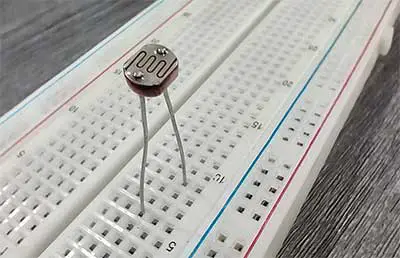
For this project, we will be using the Light Dependent Resistor or the LDR. LDRs in consumer devices and those found in most educational robotics kits are quite simple and are able to detect and measure light. A key component of the LDR is the Cadmium Sulfide or CdS. Cadmium Sulfide is a crystalline inorganic compound that is commonly used as a yellow pigment.
As the name implies, the LDR is actually a resistor. A resistor is a device that determines the flow of electricity in a circuit. It has the following properties:
- When the resistance is high, the flow of electricity is decreased
- When the resistance is low, the flow of electricity is increased.
Cadmium Sulfide is sensitive to light and this is why it can change its resistance. When light hits the CdS, its resistance becomes low, so electricity passes through the circuit easily. When there is no light, the resistance becomes high and the flow of electricity becomes restricted. The amount of electricity that flows through the circuit can then be read by the Arduino board. By measuring the changes in the flow of electricity, you are, in effect, measuring the intensity of light. If connected properly to the Arduino board, you can now make projects that reacts based on the intensity of the light that hits the Light Dependent Resistor.
The LDR sensor has a simple structure. Two electrodes, such as wires or rods, are connected to an electricity source while the sensor is nestled between the 2. The sensor is covered with a clear protective shell. These sensors are quite small, ranging from 1/5 to ½ of an inch in diameter. They normally can detect visible light between the violet and orange wavelengths.
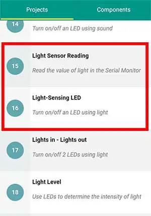
PROJECT 1: Light Sensor Reading
To test our LDR, let’s make Projects 15 and 16 of the Arduino Intro app. Project 15 will print values ranging from 0 to 1023 on the Serial Monitor.
For this project, you will need an LDR and a 10K ohm resistor. There is no permanent positive and negative side of an LDR. Instead, you will just have to choose which one will be your positive and negative side.
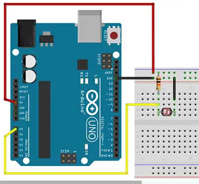
Your chosen negative side goes directly to the GND pin of the Arduino board. Your chosen positive will branch out to 2 separate pins. This side should go through a 10K ohm resistor first before connecting it to the 5V pin of the Arduino board. Another jumper wire should be connected just before the resistor, and it goes to any analog pin. In this case, we connect it to analog pin A0.
	//Read the value of a light sensor


	int pinLDR=A0;
	int val=0;

	void setup()
	{
		//initialize communication at 9600 bits per second
		Serial.begin(9600);
	}

	void loop() {
		val= analogRead(pinLDR);

		//print the value on the serial monitor
		//Go to Tools->Serial Monitor to see the values
		Serial.println(val);
		delay(100);
	}
For the code, we need to declare 2 variables. Take note of the value of the pinLDR variable. Since we are using the analog pin 0, we should write A0 instead of just a 0. This is to distinguish it from digital pin 0.
The val variable will simply hold the value of the LDR.
In the setup function, we just type in Serial.begin(9600); to enable us to write to the Serial Monitor later on. There is also no need to set the analog pin variable as INPUT because all analog pins are INPUT types by default.
val= analogRead(pinLDR);In the loop function, we just read the analog pin and save it to the val variable. Next, we print the value of the val variable to the Serial Monitor by typing Serial.println(val); A delay is added as an interval for the next reading.
PROJECT 2: Light-Sensing LED
Using Light to Turn on an LED
Our next project will let us turn on an LED when it becomes dark and turn it off when it is bright. This is a perfect application for the light sensor. This is Project 16 of the Arduino Intro app: Light-Sensing LED.
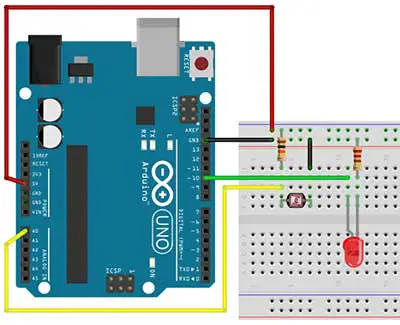
You will need 1 LDR, 1 10K ohm resistor, 1 LED, and 1 220-ohm resistor. For the circuit, you’ll just need to add 1 LED circuit to your breadboard from the previous project.
	//turn on/off an LED using the light sensor

	int pinLDR=A0;
	int pinled=10;
	int val=0;

	void setup(){
		pinMode(pinled,OUTPUT);

	}

	void loop(){
		val = analogRead(pinLDR);

		if (val <300){
			digitalWrite(pinled,HIGH);
		}
		else{
			digitalWrite(pinled,LOW);
		}
	}
In the code, we first declare 3 variables: pinLDR is the analog pin where the LDR is connected, here it is Analog pin 0. The pinled variable is for the digital pin of the LED and the val variable to hold the value of the LDR.
In the setup function, you just set up pinled as an OUTPUT pin.
The loop function centers on the if-else statement. First, we get the value of the light sensor through the analogRead() function. This is similar to the digitalRead() function, except we are reading one of the analog pins instead of a digital pin. The value is then saved in the val variable.
if (val <300){The condition in our if statement is val < 300. This is read as: if val is less than 300. The 300 here depends on your light setting. You can always modify this one with your own value. You can get the value from the previous project, Project 15. The value should be between 0 and 1023.
If the condition is true, then the LED should light up. Try to cover the LDR with your hand or a box and see if it works. You can always adjust the sensitivity of your light sensor by changing the number in the condition part of the if-else statement.
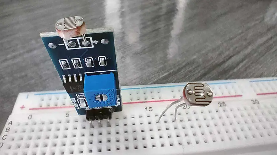
Pre-Assembled Light Sensor Module
If you don’t want to assemble your own light sensor, there is a pre-assembled module available in some electronics shops. This will help you save time when making your circuits. All you need to do is connect some jumper wires from the module to your Arduino board. Another advantage here is you can easily extend the length of your light sensor.
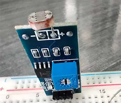
This is an example of a pre-assembled light sensor module. Notice that it already has the LDR soldered into the circuit board. This one can only output a digital signal, but some modules can send both digital and analog output. A digital output means you will be getting a 1 or 0, while analog output gives you a range from 0-1023. There is also an adjuster in the module to adjust the intensity of light before the sensor is triggered. You can turn the adjuster clockwise or counterclockwise using a screwdriver to adjust the sensitivity level.
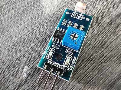
It is easy to add this module to your Arduino board. This module already has pins soldered into it. The GND pin goes to the GND pin of the Arduino board. The VCC goes to the 5V pin, and the D0 pin goes to any digital pin, except 0 and 1, which are reserved for serial communication purposes.
Here’s a sample code that you can use with your light sensor module.
//Switch an LED using a light sensor

	int lightsensor = 2;
	int PinLed = 10;
	int val=0;


	void setup()
	{
		pinMode(lightsensor, INPUT);
		pinMode(PinLed, OUTPUT);

	}

	void loop()
	{
		if(digitalRead(lightsensor) == LOW) //it is dark
		{
			digitalWrite(PinLed, HIGH);
		}
		else
		{
			digitalWrite(PinLed, LOW);
		}
	}
It basically behaves like the touch sensor from Projects 11 and 12 of the Arduino Intro app.
Just as light allows us to see things, light also enables machines to “see” in a different way. For machines, the ability to see is related to detecting light. With the addition of motors and wheels, robots can be programmed to seek a source light.