Made by: Moira Mundo
The materials you’ll be needing:
- gizDuino UNO-SE Board
- gizDuino UNO-SE Cable
- Solderless Breadboard
- 10 LEDs (preferably red and yellow)
- 21 FF Jumper Wires
- 8 MM Jumper Wires
- 1 10k ohms Resistor
- 1 Tact Switch
- 10 220 ohms Resistor
- Any cardboard-like material
- Foil
- Red Plastic Container (empty)
- Paint (Black, Red, White)
- Paint Brush
- Pen Cap
- Bottle Cap
- E-700 Glue
Step 1: Trace a rectangle onto your piece of hard paper, I used a Krispy Kreme Donut Box. You can freehand the rectangle as I did but if you’d like some reference here are the measurements:
Length: 28 cm
Height: 16.5 cm
Width: 4 cm

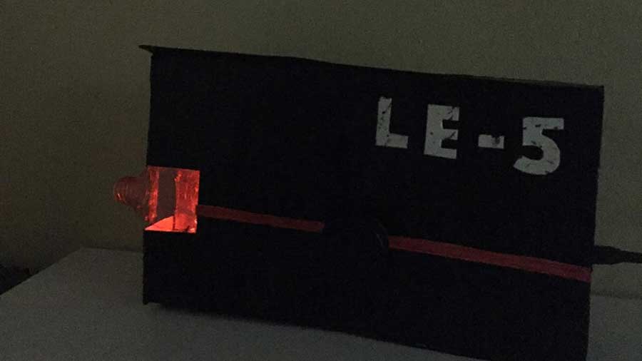
Step 2: Paint and decorate your GBE, you can customize it to however you’d like. I made mine into LE-5. That'll be much easier especially when assembling it. Leave it to dry before starting the other steps.
Step 3: If you’re lucky, you may be one of the few whose breadboard has a double-sided sticker at the bottom. Peel it off and stick it to the wrong side (unpainted) of the back piece of your GBE. Do the same thing with the gizDuino Board. Make sure to have its port face the outside, not towards the breadboard.

Step 4: Add the top and side pieces of the GBE. Make sure the port can be easily inserted.
Step 5: Cut a small square to the side piece next to the solderless breadboard. Now, cut your red plastic container and make sure it fits that part.

Step 6: Time for the fun part! Let’s add the LEDs, jumper wires, resistors, and a button. First, let’s add the LEDs. Place them horizontally across the breadboard. It’s important to place them on one side of the breadboard so that they can emit the most light possible. Next, add the 220 ohms resistors on the cathodes side of each LED, then attach each of them to the negative side of the power rail. Now, add the female jumper wires to the anodes side of each LED, make to attach the other female end of the jumper wire to the LED the other LED is partnering with. Lastly, attach 10 female jumper wires to 5 male jumper wires so each wire will have two females and one male in the middle. This will extend the jumper wires so we can work with them a lot easier. Attach each wire to the anode side of one LED, this means it’ll be perpendicular to another jumper wire.

Now, add a connected jumper wire (2 females, 1 male) to the negative side of the power rail, attach it to the GND Pin of the gizDuino Board. Now, add the connected jumper wires we made earlier to the digital pins, 3, 5, 6, 9, 10. Now that those are connected, add a tact switch to the middle area of the breadboard. Now make another connected jumper wire and place it to the same set of holes as the tact switch, connect the other end of that set of wires to the 5v Power Output Pin. Now, take your 10k ohms resistor and do the same but connect the other end to the negative side of the power rail.
Lastly, take one more set of connected jumper wires and attach it to the same set of holes as the tact switch, then connect it to digital pin 2. For extra support, I taped all my connected jumper wires together using scotch tape.

Step 7: Tape the connected wires down to the piece of cardboard then cover it with some aluminum foil. Take some more foil and roll it up into little balls just enough to make the GBE is not hollow.

Step 8: Open your Arduino Application and paste this code. This’ll be the sketch used for our GBE.
  int pinZ=10;
  int pinB=9;
  int pinE=6;
  int pinA=5;
  int pinM=3;
  int PinButton1=2;
  int val =0;


  void setup() {
    pinMode(pinZ,OUTPUT);
    pinMode(pinB,OUTPUT);
    pinMode(pinE,OUTPUT);
    pinMode(pinA,OUTPUT);
    pinMode(pinM,OUTPUT);
    pinMode(PinButton1,INPUT);
}

void loop() {
for (int x=5;x<=255;x=x+10){
  analogWrite(pinZ, x);
  delay(3.5);
  analogWrite(pinB,x);
  delay(3.5);
  analogWrite(pinE,x);
  delay(3.5);
  analogWrite(pinA,x);
  delay(3.5);
  analogWrite(pinM,x);
  delay(3.5);
}


//start of fade-out effect

for (int y=255;y>=0;y=y-10){
  analogWrite(pinZ, y);
  delay(3.5);
  analogWrite(pinB,y);
  delay(3.5);
  analogWrite(pinE,y);
  delay(3.5);
  analogWrite(pinA,y);
  delay(3.5);
  analogWrite(pinM,y);
  delay(3.5);
}

val=digitalRead(PinButton1);

if(val==HIGH)
{
  for (int z=5;z<=255;z=z+10){
    analogWrite(pinZ, z);
    delay(10);
    analogWrite(pinB,z);
    delay(10);
    analogWrite(pinE,z);
    delay(10);
    analogWrite(pinA,z);
    delay(10);
    analogWrite(pinM,z);
    delay(10);
  }

  //start of fade-out effect
  for (int i=255;i>=0;i=i-10){
    analogWrite(pinZ, i);
    delay(10);
    analogWrite(pinB,i);
    delay(10);
    analogWrite(pinE,i);
    delay(10);
    analogWrite(pinA,i);
    delay(10);
    analogWrite(pinM,i);
    delay(10);
  }

  for (int k=5; k<=255;k=k+10){
    analogWrite(pinZ, k);
    delay(5);
    analogWrite(pinB,k);
    delay(5);
    analogWrite(pinE,k);
    delay(5);
    analogWrite(pinA,k);
    delay(5);
    analogWrite(pinM,k);
    delay(5);
  }

  //start of fade-out effect

  for (int n=255;n>=0;n=n-10){
    analogWrite(pinZ, n);
    delay(5);
    analogWrite(pinB,n);
    delay(5);
    analogWrite(pinE,n);
    delay(5);
    analogWrite(pinA,n);
    delay(5);
    analogWrite(pinM,n);
    delay(5);
  }

  for (int m=5;m<=255;m=m+10){
    analogWrite(pinZ, m);
    delay(3.5);
    analogWrite(pinB,m);
    delay(3.5);
    analogWrite(pinE,m);
    delay(3.5);
    analogWrite(pinA,m);
    delay(3.5);
    analogWrite(pinM,m);
    delay(3.5);
  }

  //start of fade-out effect

  for (int p=255;p>=0;p=p-10){
    analogWrite(pinZ, p);
    delay(3.5);
    analogWrite(pinB,p);
    delay(3.5);
    analogWrite(pinE,p);
    delay(3.5);
    analogWrite(pinA,p);
    delay(3.5);
    analogWrite(pinM,p);
    delay(3.5);
  }

  for (int r=5;r<=255;r=r+10){
    analogWrite(pinZ, r);
    delay(1);
    analogWrite(pinB,r);
    delay(1);
    analogWrite(pinE,r);
    delay(1);
    analogWrite(pinA,r);
    delay(1);
    analogWrite(pinM,r);
    delay(1);
  }

  //start of fade-out effect

  for (int s=255;s>=0;s=s-10){
    analogWrite(pinZ, s);
    delay(1);
    analogWrite(pinB,s);
    delay(1);
    analogWrite(pinE,s);
    delay(1);
    analogWrite(pinA,s);
    delay(1);
    analogWrite(pinM,s);
    delay(1);
  }

      delay(10000);
 }
}
Step 9: Test it out! You know it’s working when the lights start fading in and out and it switches to a new effect when the button is pressed. Now, once you’ve tested it and made sure it works, stuff it with even more foil, we want as much light to reflect as possible.

Step 10: Now add the finishing touches! Retrieve the top part of your GBE and poke a hole through it, make sure it’s big enough that you can see the tact switch. Take the pen cap and glue it to the bottle cap, paint it if needed. Place the top and final piece of the GBE over the foil and take the button that we just made and glue it to the tact switch through the hole. Glue all the sides and pieces well, we don’t want our weapon to fall apart during battle! Repaint if needed.


That’s it you’re all, done! It should fade in and out, meaning it’s charged. When you press the button 5 times, it should switch to its shooting effect. Then, wait 10 seconds for it to fade in and fade out again. That part means it’s recharging, hehe! Hope you like your new GBE! Not only it’s a futuristic weapon but also a cool décor piece. That would be all, thanks for reading my article!

I felt empowered during the making of my product. I imagined I was an engineer creating weapons for my team who were going to fight bad guys and evil robots and like we were the last hope for humanity. It was really fun, exhausting, but exhilarating! The overall experience was great, I just pulled some hairs because the coding took so long, it literally took me 24 hours, more or less, trial and error included. However, it was all worth it in the end. I would also like to add that because of me being sleep-deprived, I was so excited to finally make my GBE, I completely forgot to document and take photos. Sadly, LE-5 is now disassembled, quietly blinking, as she knows she’s served her purpose, rest in peace fallen soldier.
On a less depressing note, my realization after making the exit product was that I am actually very capable of robotics. The materials were very intimidating at first, especially the codes, but with time and experience, it became easy to handle and I am very thankful for all the learning materials provided because they helped me understand the topics more.
This experience made me realize that I am capable, and I can do things I never knew I could do.


