Made by Maritess Marmito.
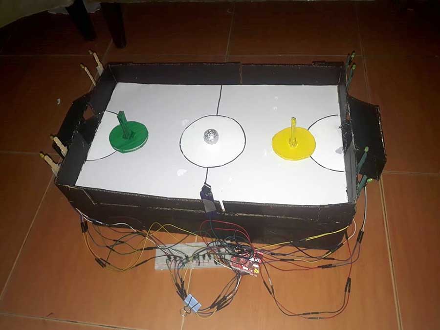
My Exit Product for the second quarter is a DIY Hockey game. This is a two-player game in which both players hold a handle that is used to push the ball, which you must shoot into your opponent's goal to earn a point. This is where the two sensors, the piezo buzzer, and the LEDs, come into play. In this project, I used two sensors: a touch sensor and an infrared sensor.
These sensors will be positioned at the base of each goal. When the ball enters the goal, the sensor detects it and emits a sound from the piezo buzzer, while the four LEDs in each goal will light up. Furthermore, if no object is detected by those sensors, the piezo buzzer will stop making noise, and as well as the LEDs will stop lighting up. The LEDs are specifically attached beside the goal and are hung in the popsicle stick that serves as the base, and I simply used duct tape to keep the LEDs in place while the buzzer was placed in the center of one side of the game.
Also, the connections are just beside the game, but we can try to make it hidden at the bottom of the game, which is what I would do if I had more wires left to extend the length of each wire. You can even play this game without using sensors or LEDs, but you must be aware of when you earned a point and when your opponent earned a point.
The purpose of the LEDs, piezo buzzer, and sensors is to serve as a reminder to the players who have earned a point.
Materials Needed
For the lights
- 8 LEDs
- Arduino Board
- USB interface
- Breadboard
- Jumper Wires
- Resistors
- Infrared sensor
- Touch sensor
- Piezo Buzzer
For the game itself
- Illustration bored
- Used box
- Glue gun and Glue stick
- Popsicle sticks
- Glue
- Scissors and Cutter
- Paint and paintbrush
- Foil
STEP-BY-STEP PROCESS
For the game :
STEP 1
Gather all the materials.
STEP 2
Take the box and cut it down to the size you want for the game. Then, for the box's center, I cut an illustration board in the same shape so that the play area would be sturdier.


STEP 3
Draw the game's design and trace it using a marker.

STEP 4
Paste the illustration board to the box, then paste the sides to complete the look.

STEP 5
I built the game's foundation to make it more durable. I simply pasted two large rectangular boxes and placed them at the side(bottom) of the game. Then I cut two more rectangular shapes and placed them at the bottom of the game (X shape) to make it sturdier.


STEP 6
Paint the box. Create the goal using a rectangular shape of an illustration board and then paste it to both sides by making a hole on both sides. I cut a tiny square shape at the bottom of one of the rectangular illustration boards to be where the sensors will be attached. (There are two goals for this game because it is a 1 vs 1 person).


STEP 7
Make a ball out of foil ( I created 1 ball and 2 things that the players will use to goal).


STEP 8
Create a handle for each player. In this case, I cut 6 circular shapes out of the illustration board and layered three of them on top of each other. Then, for its handle, I simply cut 10 rectangular shapes of illustration board and layered four of them on top of each other. I then simply use the glue gun to adhere the handle to the circles. I then painted it yellow and green.


For the Wirings, LEDs, and sensors :
STEP 1
I encoded the following code:
  //For exit product
  //Control 8 LEDs using a touch sensor and ir sensor with buzzer

  int touchsensor = 4;
  int ir = 3;
  int led1=5, led2 =6, led3=7, led4=8,led5=9,led6=10,led7=11,led8=12;
  int buzzer = 2;
  int val=0;

  void setup()
  {
    pinMode(touchsensor, INPUT);
    pinMode(ir, INPUT);
    pinMode(led1, OUTPUT);
    pinMode(led2, OUTPUT);
    pinMode(led3, OUTPUT);
    pinMode(led4, OUTPUT);
    pinMode(led5, OUTPUT);
    pinMode(led6, OUTPUT);
    pinMode(led7, OUTPUT);
    pinMode(led8, OUTPUT);
    pinMode(buzzer, OUTPUT);

  }

  void loop()
  {
    //both sensors are triggered
    //You may need to check the serial monitor for the 1 and 0 values
    //The 1 and 0 may depend on the type of sensor
    //feel free to change 1 to 0 or vice-versa depending on your project

    if(digitalRead(touchsensor) == 1 && digitalRead(ir) == 1)
    {
      digitalWrite(led1, LOW);
      digitalWrite(led2, LOW);
      digitalWrite(led3, LOW);
      digitalWrite(led4, LOW);
      digitalWrite(led5, HIGH);
      digitalWrite(led6, HIGH);
      digitalWrite(led7, HIGH);
      digitalWrite(led8, HIGH);
      tone(buzzer,800,500); //produce sound for 500 milliseconds
      //add a "quiet" time of 500 milliseconds
      delay(1000);
    }
    else if (digitalRead(touchsensor) == 1 && digitalRead(ir) == 0)
    {
      digitalWrite(led1, HIGH);
      digitalWrite(led2, HIGH);
      digitalWrite(led3, HIGH);
      digitalWrite(led4, HIGH);
      tone(buzzer,800,500); //produce sound for 500 milliseconds
      //add a "quiet" time of 500 milliseconds
      delay(1000);
      digitalWrite(led5, HIGH);
      digitalWrite(led6, HIGH);
      digitalWrite(led7, HIGH);
      digitalWrite(led8, HIGH);
      tone(buzzer,800,500); //produce sound for 500 milliseconds
      //add a "quiet" time of 500 milliseconds
      delay(1000);
    }
    else if (digitalRead(touchsensor) == 0 && digitalRead(ir) == 1)
    {
      digitalWrite(led1, LOW);
      digitalWrite(led2, LOW);
      digitalWrite(led3, LOW);
      digitalWrite(led4, LOW);
      digitalWrite(led5, LOW);
      digitalWrite(led6, LOW);
      digitalWrite(led7, LOW);
      digitalWrite(led8, LOW);

    }
    else if (digitalRead(touchsensor) == 0 && digitalRead(ir) == 0)
    {
      digitalWrite(led1, HIGH);
      digitalWrite(led2, HIGH);
      digitalWrite(led3, HIGH);
      digitalWrite(led4, HIGH);
       tone(buzzer,800,500); //produce sound for 500 milliseconds
      //add a "quiet" time of 500 milliseconds
      delay(1000);
      digitalWrite(led5, LOW);
      digitalWrite(led6, LOW);
      digitalWrite(led7, LOW);
      digitalWrite(led8, LOW);

    }
  }
STEP 2
Gather all of the sensors and the piezo buzzer, then insert each of them with jumper wires.

STEP 3
Connect GND and 5V to the breadboard.

STEP 4
Connect all of the jumper wires from each sensor and the piezo buzzer to their respective Arduino and breadboard pins. (GND pin goes to the GND pin of the Arduino board, VCC goes to the 5V pin, D0 pin goes to any digital pin, except 0 and 1, I/O – any digital pin (except 1 and 0), and OUT pin goes to any digital pin, except 0 and 1.

STEP 5
To make it longer, connect the LEDs to a jumper wire. Then repeat for all of the LEDs that will be used.

STEP 6
Connect the jumper wires of each LED to the breadboard, followed by the 220k Ohm resistors on the LED's negative side. Then, for each LED (anode of the LED), connect it to the digital pins of your Arduino board using jumper wires.


In my case, I was using the two sides of the breadboard and so I have to connect jumper wires with them to let the electricity pass through.

STEP 7
Stick the Popsicle sticks on the sides, then the LEDs, and finally connect all of the wirings on the game board.

STEP 8
Upload the code to the Arduino board, and you'll have the go signal to play with it already.


I'm having a lot more fun making my exit product than I was in the first quarter because I already know the basics of robotics and what the potential errors are if my product doesn't work. Another reason I had a lot of fun was that the product was a game, and seeing and playing with the finished product with my sister was enjoyable. And even while developing the product, all I could think about was the finished product, so I was really motivated to finish it because I was so eager to play it.
Aside from that, I had some difficulties along the way because I needed to finish my exit product by Friday because we are going to visit my Lola and Lolos' house in Medina because we were unable to pay them a visit to the cemetery last November 1. And so, with the pressure that I put on myself to finish it by Friday, it was extremely difficult and exhausting for me. Despite the fact that I planned some activities ahead of time so that I would have plenty of time to work on my exit product. That really greatly helped me in finishing my exit product by Friday.
It was also difficult because I got my vaccine yesterday (Thursday) and the next day, today (Friday), my body was weak, my arms were swollen, and I also had back pain and a headache, but I still gave it my all and fought through the difficulties I had encountered. Furthermore, after creating my exit product, I realized that it is better to do things ahead of time and not procrastinate because unexpected and expected things may and will occur. We have to pay our Lola and Lolo a visit to the cemetery by Saturday, just like in my case.
Another thing is that my vaccination schedule was set for Thursday and I was only informed about it the night before, but the good thing is that I was able to do some activities ahead of time so that I wouldn't be overburdened with activities the next day and could focus on finishing my exit product. Finally, I realized that I am the type of person who does not give up easily and is very motivated to complete each task, and I will do my best to continue being this type of person because it not only benefits me now but will have an impact in the future.
Looking at my exit product, I was extremely proud of myself because the process was difficult, but at the end of the day, I was able to complete it on time. Laban lang talaga and with God’s grace and guidance I can do things.


